Building an Arduino Robot, Part VI: Remote Control
Posted by
on under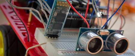
Welcome to the sixth article in the tutorial series in which I'm building a remote controlled Arduino based vehicle robot.
Here is the list of articles I have published so far:
- Part I: Hardware Components
- Part II: Programming the Arduino
- Part III: Assembling the Robot
- Part IV: A (Not So) Basic Robot Firmware
- Part V: Avoiding Obstacles
- Part VI: Remote Control (this article)
In the past two articles I have implemented the motor and distance sensor control for my little robot vehicle, using sound software development techniques that make this project easier to write and to maintain.
Today I will be implementing the most challenging (and let's admit it, also the most fun) aspect of my project: the ability to remotely control the robot from a smartphone over Bluetooth.
A small improvement
Before I get into the main topic of this article I'm going to tell you about a small modification I've made to my robot that helps with the remote control functionality.
If you recall the article in which I showed you how to program the Bluetooth module, it is not possible to upload a sketch over USB while the Bluetooth module is connected to pins 0 and 1, because those pins are used by the USB/serial communication.
When I started writing the remote control code I became a bit frustrated with having to constantly connect and disconnect Bluetooth and USB. To avoid this hassle I decided to use the SoftwareSerial.h library that comes with the Arduino software to move the Bluetooth connection to a different set of pins.
The change is pretty simple. I moved the connections from the Bluetooth module going into pins 0 and 1 to analog pins 2 and 3 (numbered 16 and 17), which are unused. Then I created a SoftwareSerial object at the top of the sketch:
#define BT_RX_PIN 16
#define BT_TX_PIN 17

#include <SoftwareSerial.h>
SoftwareSerial BTSerial(BT_RX_PIN, BT_TX_PIN);
And then, instead of using the Serial object like in my previous tests, I used the BTSerial object. The setup() in my sketch then changed to:
void setup()
{
    Serial.begin(9600);
    BTSerial.begin(9600);
}
Why keep the Serial.begin() call? Because I elected to keep sending the logging output to the regular serial interface. I now have access to two serial ports, so I will use the Bluetooth connection for remote commands and the USB one for logging and debugging output. Neat!
With the Bluetooth module connected in this way there is no collision with the USB serial interface so I could keep the USB cable connected at all times while developing and testing.
Remote Control device driver
Like in the previous articles, I'm going to start by designing a device driver that can abstract the main sketch from having to deal directly with hardware.
But this case is a little different. We really have two separate pieces to abstract. The most obvious is the communication method. My robot uses Bluetooth, but this is not the only mechanism by which a robot can be controlled. At least I can think of three more, WiFi, RF and infrared. I clearly need a device driver that can read remote commands, regardless of the wireless technology used.
The second, and less obvious dimension to this problem is the remote protocol. Different remote controllers will use different command codes to mean the same thing. For example, one remote control may send the command to turn left as a byte, maybe the letter "L". Another controller with a numeric keypad configuration may use "4" for the same thing. Another, joystick inspired remote control may not support a direct "go left" command at all and may just send instructions as vectors in a two-dimensional grid, so going left would be given as two numbers, (-1, 0). I do not really want to deal with these differences in the high-level robot code because that will make my code more complex. So clearly a driver that can hide these protocol differences from the main sketch is also needed.
So do I need two different drivers, then? Let's think about how the main sketch will obtain remote control commands. Ideally I want something simple, like a getCommand() function that just returns the next command if one is available. If that's all I need then it seems all the main sketch requires is access to one remote control driver that somehow knows how to receive remote controls and interpret them.
There are two ways this could work. If I implement two drivers, for communication and protocol separately, then the main sketch will only talk to the protocol driver, and it will be the protocol driver's job to know what communication driver to talk to. This provides great flexibility, because the same protocol can easily be supported over different communication channels.
And what would be the alternative? I could embed the communication part inside the protocol driver. This is less flexible because now the remote protocol is tied to a particular communication channel. But on the other side it is simpler to implement because I don't need to define a device driver for communication channels, each protocol driver does its own thing to read remote commands.
Which of these options is better? It really depends. If I was working with standard protocols that remote controls of different kinds implement, then having separate protocol and communication drivers makes sense. In this case, however, I believe the kinds of remote controls that I will find are mostly using proprietary protocols. My impression is that I will never need to use a protocol driver with more than one communication method.
Based on this analysis, I'm going to go with the simpler option for now, one driver for the combined protocol and communication handling. I can always break the driver into two in the future if I find the need.
The remote control driver interface
Given the variety of remote controls out there, I need to find a common format that all the remote drivers can use to represent commands. For the purpose of driving a vehicle, I can think of three types of remote controls that I might ever need to support:
- Keypad based: the robot is controlled with directional keys or buttons.
- Joystick based: the robot is controlled with a multi-directional stick that returns
(X,Y)coordinates inside a circle. - Slider based: the robot is controlled with two sliders, in two possible configurations:
- each slider controls one side of the vehicle
- one slider controls forward/backward motion, the other controls left and right motion.
In all cases it is safe to assume that in addition to the directional control there are a few function buttons.
As you can see there are significant differences between the types of remote controls, so the job of defining a common format for all of them is not easy.
Obviously I cannot indicate direction with simple forward, backward, left and right commands, since many remote controls can provide a finer degree of directional control and it would be a pity to ignore all that extra information.
So I have to pick one of the more advanced remote control data representations. The one that translates more easily into motor instructions for my vehicle is the one where the controller uses two sliders, each controlling one side of the vehicle. This directly translates into speeds for my two motors, so the application can simply send the data from the remote control into the motors. Since I like to keep the main sketch simple this is the approach that I'm going to take.
But there is a downside to selecting a single data representation for all types of controllers. For remote controls that don't use the chosen format a conversion will be needed. To help with this task the base driver class will provide the conversion functions for all types of remote controls.
Let's take a look at the definition of the remote control device driver interface:
/**
 * @file remote_control.h
 * @brief remote control driver definition for the Michelino robot.
 * @author Miguel Grinberg
 */

namespace Michelino
{
    class RemoteControlDriver
    {
    public:
        /**
          * @brief abstract representation of a remote command.
          */
        struct command_t {
            enum key_t { keyNone, keyF1, keyF2, keyF3, keyF4 };
            int left;   /**< left side speed, between -255 and 255. */
            int right;  /**< right side speed, between -255 and 255. */
            key_t key;  /**< function key. */

            command_t() : left(0), right(0), key(keyNone) {}

            // conversion functions
            void goForward();
            void goBack();
            void turnLeft();
            void turnRight();
            void stop();
            void leftAndRightSliders(int l, int r);
            void forwardBackAndLeftRightSliders(int fb, int lf);
            void joystick(int x, int y);
        };

        /**
          * @brief Class constructor.
          */
        RemoteControlDriver() {}

        /**
         * @brief Return the next remote command, if available.
         * @param cmd a reference to a command_t struct where the command
         *   information will be stored.
         * @return true if a remote command is available, false if not.
         */
        virtual bool getRemoteCommand(command_t& cmd) = 0;
    };
};
For this driver I will use an auxiliary struct that represents a remote command. The representation of a command includes left and right slider values and a possible function key. A remote control driver can provide up to four function keys, all listed in the enum definition.
The getRemoteCommand() method will be implemented by remote control drivers. It takes a reference to a command_t structure and is expected to fill it out appropriately, using one of the provided conversion functions if necessary.
As far as conversion functions I know I'm going to need to cover the basic remotes, with four commands to represent the four directions that they provide and one more to make the robot stop. For the more advance remotes I need to handle left and right side sliders (which really require no conversion, but for the sake of abstraction and consistency I will provide a function as well) and forward/back and left/right sliders, which as you will see in a moment also covers the joystick type controllers.
Let's look at the implementation of the conversions:
            void goForward()
            {
                left = right = 255;
            }
            void goBack()
            {
                left = right = -255;
            }
            void turnLeft()
            {
                left = -255;
                right = 255;
            }
            void turnRight()
            {
                left = 255;
                right = -255;
            }
            void stop()
            {
                left = right = 0;
            }
            void leftAndRightSliders(int l, int r)
            {
                left = l;
                right = r;
            }
            void forwardBackAndLeftRightSliders(int fb, int lr)
            {
                left = fb - lr;
                right = fb + lr;
                if (left < -255)
                    left = -255;
                else if (left > 255)
                    left = 255;
                if (right < -255)
                    right = -255;
                else if (right > 255)
                    right = 255;
            }
            void joystick(int x, int y)
            {
                forwardBackAndLeftRightSliders(y, x);
            }
All but one of these are trivial. The first five just set the left and right sides appropriately, while the sixth copies the values given as arguments, since these match the internal data representation.
The next conversion is the one that requires some thought. Here I have a controller that has two sliders, one vertical to move forward or backward and one horizontal to move left or right. Both sliders can be operated independently, so at any given time the remote control provides forward/backward speed and left/right turn values. Somehow I need to use these two values to derive independent left and right values to power the motors.
The algorithm that I came up with for this conversion is relatively simple. The forward/backward slider is transferred directly into both sides, so that when there is no left/right motion the vehicle moves straight forward or backward. Then the value of the left/right slider is added to the right motor and subtracted from the left motor. If the left/right slider is positioned towards the left then it's value will be negative, so adding it to the right side will lower the power of that side, while subtracting it from the left side will make the left side stronger. And these changes will just make the robot go towards the left side, which is what I want. Of course, the reverse happens when the left/right slider is moved towards the right.
The last conversion function is for joystick type controllers. The good news is that I realized that the joystick's (x,y) coordinate values are really the same as the left/right and forward/backward values in the previous conversion functions, so I can use the same function for those.
Remote control driver implementation
My choice of controller is a free Android app called BlueStick. Here is a screenshot of this app:
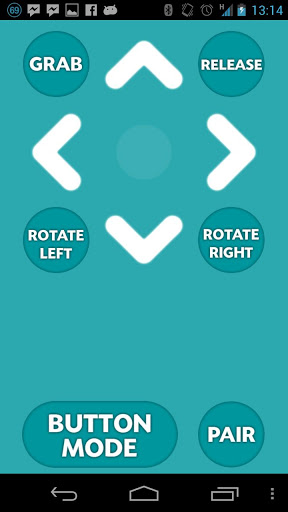
This is a very simple controller with five directional commands and six function buttons. The directional commands can be triggered by touching arrow buttons on the screen or by tilting the phone. The app documentation provides the codes that are sent over Bluetooth for each of the commands:
'0' = Stop
'8' = Up
'2' = Down
'4' = Left
'6' = Right
'A' = Auto Grab
'B' = Auto Release
'C' = Grab
'D' = Release
'E' = Rotate Left
'F' = Rotate Right
Note that while this remote control app gives specific names to its six function keys, I will ignore those names and just define my own meaning for these keys.
The above list defines the protocol for this remote control, so this is really all I need to know to be able to implement this driver. So here is the code for the BlueStick driver:
/**
 * @file bluestick_remote_control.h
 * @brief remote control driver for the BlueStick Android remote control app.
 * @author Miguel Grinberg
 */

#include "remote_control.h"

namespace Michelino
{
    class RemoteControl : public RemoteControlDriver
    {
    public:
        /**
          * @brief Class constructor.
          */
        RemoteControl() : RemoteControlDriver(), lastKey(command_t::keyNone) {}

        virtual bool getRemoteCommand(command_t& cmd)
        {
            cmd.stop();
            cmd.key = command_t::keyNone;

            if (BTSerial.available() <= 0)
                return false; // no commands available
            char ch = BTSerial.read();
            switch (ch) {
                case '8': // up
                    cmd.goForward();
                    break;
                case '2': // down
                    cmd.goBack();
                    break;
                case '4': // left
                    cmd.turnLeft();
                    break;
                case '6': // right
                    cmd.turnRight();
                    break;
                case 'A': // function key #1
                case 'C':
                    cmd.key = command_t::keyF1;
                    break;
                case 'B': // function key #2
                case 'D':
                    cmd.key = command_t::keyF2;
                    break;
                case 'E': // function key #3
                    cmd.key = command_t::keyF3;
                    break;
                case 'F': // function key #4
                    cmd.key = command_t::keyF4;
                    break;
                default:
                    break;
            }
            if (cmd.key != command_t::keyNone && cmd.key == lastKey) {
                // repeated key, ignore it
                return false;
            }
            lastKey = cmd.key;
            return true;
        }

    private:
        command_t::key_t lastKey;
    };
};
If you need a refresher on how the Bluetooth slave module works feel free to reread my previous post about the topic.
This implementation is extremely simple. If the BTSerial class has a character in its queue, then I read it, and depending on what character it is I configure the command, using conversion functions for the directional commands or the key constants for the function keys. I have six function keys in this remote control app, but I decided to just use four in my driver, so I map the two extra keys as duplicates of another two.
I also need to explain what the lastKey member variable is for. As a test I connected the BlueStick app running on my cell phone to a Bluetooth terminal running on another phone, just to confirm that the commands the app sends are in alignment with the documentation. I found that they did match, but also found that the app is constantly sending commands. There isn't really a point in having to handle repeated keys, so I added the lastKey variable to keep track of the last key received. If I find that the new key is the same as the previous one then I just throw it away as a duplicate.
Another important thing to note about this implementation is that it tries to be tolerant of unknown codes. At the start I initialize the command structure as a stop with no function keys. If I receive an unknown character then the sketch will receive a stop command, which will make the robot stop and wait for more commands.
With this basic driver implemented I have enough to incorporate and test the remote control functionality into my sketch, so that's what I'm doing next.
Design the Remote Control Feature
But before I delve into code again, let's discuss how is the robot going to behave, because in the previous article I ended up with a really nice and neat firmware that made the robot run standalone avoiding obstacles, and I'm not really interested in throwing all that code away!
My goal for the remote controlled robot is to incorporate the automated mode I wrote in the previous article as an option that can be enabled with a special remote command. In lack of a better name I'm going to call the automatic mode the "Roomba" mode (I hope I don't get sued for copyright infringement!).
After some consideration I designed the following flow chart for how the robot will operate under remote control:
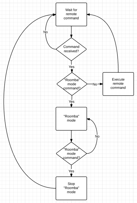
Translating the chart into words this is what I'm going to do:
- The robot will begin by listening for remote commands, without moving.
- If a command is received it will be executed, and then it will go back to listen for more commands.
- There will be a "Roomba" mode command that acts as a toogle.
- Any other commands sent while the robot is in "Roomba" mode will be ignored.
Adding remote control to the sketch
Okay, now I will move on to the most exciting part, which is to actually write the code to make the robot follow the remote commands.
Starting from the sketch as I left it in the previous article I begin by adding the remote control driver class to the top of the sketch, where all the drivers are:
#define ENABLE_BLUESTICK_REMOTE_CONTROL_DRIVER

#ifdef ENABLE_BLUESTICK_REMOTE_CONTROL_DRIVER
#include "bluestick_remote_control.h"
#define REMOTE_CONTROL_INIT
#endif
This class does not take any arguments to initialize, but I can't really be sure other drivers will be the same, so I keep the same style I used in previous drivers and just make the initialization constant empty this time.
Now I can add a remote control object to the Robot class:
private:
    RemoteControl remoteControl;
And I can initialize it in the Robot class constructor:
    Robot()
        : leftMotor(LEFT_MOTOR_INIT), rightMotor(RIGHT_MOTOR_INIT),
          distanceSensor(DISTANCE_SENSOR_INIT),
          distanceAverage(TOO_CLOSE * 10),
          remoteControl(REMOTE_CONTROL_INIT)
    {
        initialize();
    }
I had been using the concept of states to know if the robot was moving or turning. I now need to have an additional state for when the robot is under remote control:
private:
    enum state_t { stateStopped, stateMoving, stateTurning, stateRemote };
And since I have functions stop(), move() and turn() to enable the other states I should be consistent and have one to enter the remote control state:
    void remote()
    {
        leftMotor.setSpeed(0);
        rightMotor.setSpeed(0);
        state = stateRemote;
    }
I also had the tiny functions that returned true if a given state was enabled, to help make the code a bit more readable. Again, to be consistent I need one for the new state:
bool remoteControlled() { return (state == stateRemote); }
To initialize the robot I simply put it in remote mode:
    void initialize()
    {
        randomSeed(analogRead(RANDOM_ANALOG_PIN));
        remote();
    }
And finally, I have a new version of my run() method that does all the fun stuff:
    void run()
    {
        unsigned long currentTime = millis();
        int distance = distanceAverage.add(distanceSensor.getDistance());
        RemoteControlDriver::command_t remoteCmd;
        bool haveRemoteCmd = remoteControl.getRemoteCommand(remoteCmd);
        log("state: %d, currentTime: %lu, distance: %u remote: (%d,l:%d,r:%d,k:%d)\n",
            state, currentTime, distance,
            haveRemoteCmd, remoteCmd.left, remoteCmd.right, remoteCmd.key);

        if (remoteControlled()) {
            if (haveRemoteCmd) {
                switch (remoteCmd.key) {
                case RemoteControlDriver::command_t::keyF1:
                    // start "roomba" mode
                    move();
                    break;
                case RemoteControlDriver::command_t::keyNone:
                    // this is a directional command
                    leftMotor.setSpeed(remoteCmd.left);
                    rightMotor.setSpeed(remoteCmd.right);
                    break;
                default:
                    break;
                }
            }
        }
        else {
            // "roomba" mode
            if (haveRemoteCmd && remoteCmd.key == RemoteControlDriver::command_t::keyF1) {
                remote();
            }
            else {
                if (moving()) {
                    if (obstacleAhead(distance))
                        turn(currentTime);
                }
                else if (turning()) {
                    if (doneTurning(currentTime, distance))
                        move();
                }
            }
        }
    }
While this new version of run() may seem scary at first, I assure you that only a small portion is new, a good part of it came from the previous article.
I begin by getting all the inputs that I'm going to need, which are the current time, averaged distance sensor reading and remote control command. In case I need to do debugging at some point I kept the log statement I had before, enhanced to include remote control data as well.
For the remote control I have to note if I have received a command or not. This is what haveRemoteCmd does. If this variable is true then the remoteCmd struct holds the command data. If the variable is false then remoteCmd has an undefined value and should not be used.
Once I gathered all my inputs I move on to control the robot behavior. In this new version of the sketch there are two different operating modes. The "Roomba" mode was introduced in the previous article, while today I'm obviously I'm adding the remote control mode.
The if (remoteControlled()) statement takes care of differentiating between the two modes. The if portion deals with the remote control mode, while the else portion does the "Roomba" mode.
Let's look at the part that handles the remote control in detail:
            if (haveRemoteCmd) {
                switch (remoteCmd.key) {
                case RemoteControlDriver::command_t::keyF1:
                    // start "roomba" mode
                    move();
                    break;
                case RemoteControlDriver::command_t::keyNone:
                    // this is a directional command
                    leftMotor.setSpeed(remoteCmd.left);
                    rightMotor.setSpeed(remoteCmd.right);
                    break;
                default:
                    break;
                }
            }
This is extremely simple. If there is a remote command available I then look at the key value that came with it. If the key is keyF1 value then I enable "Roomba" mode by calling move() (see the previous article for an explanation of this method). If the command came without a key (keyNone) then it is a directional command, so all I do is move the left and right values from the remote command into the motors. That's it! Believe it or not this short piece of code fully handles the remote control of the vehicle!
The "Roomba" mode handling is mostly the same as in the previous article, with the exception that I removed the 30 second timeout handling that I had in that version and replaced it with this:
            if (haveRemoteCmd && remoteCmd.key == RemoteControlDriver::command_t::keyF1) {
                // switch back to remote mode
                remote();
            }
            else {
                // ...
            }
And this code simply switches back to remote mode if a remote command is available and its key is keyF1. The rest of this part deals with the "Roomba" mode logic, and this did not change from the previous version of the sketch.
A more advanced remote control driver
To end this article I'm going to implement a second remote control driver. My choice is RocketBot, another Android app. Here is a screenshot of RocketBot:
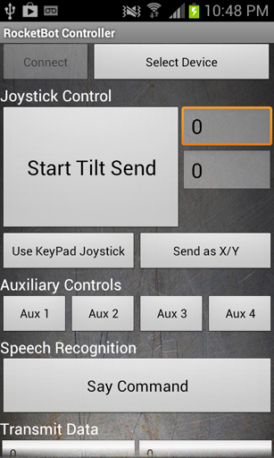
RocketBot offers several different remote control interfaces:
- Keypad: five buttons for forward, backward, left, right and stop. Exactly like the BlueStick app I implemented above.
- Joystick: X and Y values obtained from the phone accelerometer.
- Left/Right: individual controls for left and right motors, calculated from the phone accelerometer input.
The documentation describes the communication protocol in detail. For this controller all commands have two bytes, an operation byte and a data byte. A quick summary of the control codes I will be implementing (not the full list) is below:
"D1","D2","D3","D4","D5": Forward, Left, Right, Backward, and Stop respectively."A1","A2","A3","A4": Four auxiliary function buttons."X<number>","Y<number>": Joystick position. Values come in the 0-200 range, with 100 being the center position, 200 being full speed backward or right and 0 being full speed forward or left."L<number>","R<number>": Left/Right controls. Values come in the 0-200 range, with 100 being the center position, 200 being full speed forward and 0 being full speed backward, on each of the sides.
The implementation is a bit more complex than the BlueTick remote, but follows more or less the same style. Here is the full driver implementation:
/**
 * @file rocketbot_remote_control.h
 * @brief remote control driver for the RocketBot Android remote control app.
 * @author Miguel Grinberg
 */

#include "remote_control.h"

namespace Michelino
{
    class RemoteControl : public RemoteControlDriver
    {
    public:
        /**
          * @brief Class constructor.
          * @param from the value in the 0-100 range that maps to 0 in remote control units.
              Any values below from will be interpreted as 0.
          * @param to the value in the 0-100 range that maps to 255 in remote control units.
              Any values above to will be interpreted as 255.
          */
        RemoteControl(int from, int to) : RemoteControlDriver(),
            scaleFrom(from), scaleTo(to),
            lastKey(command_t::keyNone), lastX(100), lastY(100), lastL(100), lastR(100) {}

        virtual bool getRemoteCommand(command_t& cmd)
        {
            cmd.stop();
            cmd.key = command_t::keyNone;

            if (BTSerial.available() < 2)
                return false; // no commands available
            unsigned char ch = BTSerial.read();
            unsigned char data = BTSerial.read();
            switch (ch) {
                case 'D': // keypad
                    switch (data) {
                    case 1:
                        cmd.goForward();
                        break;
                    case 2: // down
                        cmd.turnLeft();
                        break;
                    case 3: // left
                        cmd.turnRight();
                        break;
                    case 4: // right
                        cmd.goBack();
                        break;
                    case 5: // stop
                    default:
                        cmd.stop();
                        break;
                    }
                    break;
                case 'X':
                    lastX = data;
                    cmd.joystick(scale(lastX), -scale(lastY));
                    lastL = lastR = 100;
                    break;
                case 'Y':
                    lastY = data;
                    cmd.joystick(scale(lastX), -scale(lastY));
                    lastL = lastR = 100;
                    break;
                case 'L':
                    lastL = data;
                    cmd.leftAndRightSliders(scale(lastL), scale(lastR));
                    lastX = lastY = 100;
                    break;
                case 'R':
                    lastR = data;
                    cmd.leftAndRightSliders(scale(lastL), scale(lastR));
                    lastX = lastY = 100;
                    break;
                case 'A': // function keys
                    switch (data) {
                    case 1:
                        cmd.key = command_t::keyF1;
                        break;
                    case 2:
                        cmd.key = command_t::keyF2;
                        break;
                    case 3:
                        cmd.key = command_t::keyF3;
                        break;
                    case 4:
                        cmd.key = command_t::keyF4;
                        break;
                    }
                    break;
                default:
                    break;
            }
            if (cmd.key != command_t::keyNone && cmd.key == lastKey) {
                // repeated key, ignore it
                return false;
            }
            lastKey = cmd.key;
            return true;
        }

    private:
        int scale(int value)
        {
            value -= 100;
            if (value >= 0) {
                if (value <= scaleFrom)
                    return 0;
                else if (value >= scaleTo)
                    return 255;
                return (value - scaleFrom) * 255 / (scaleTo - scaleFrom);
            }
            else {
                if (-value <= scaleFrom)
                    return 0;
                else if (-value >= scaleTo)
                    return -255;
                return -(-value - scaleFrom) * 255 / (scaleTo - scaleFrom);
            }
        }

    private:
        int scaleFrom;
        int scaleTo;
        command_t::key_t lastKey;
        int lastX;
        int lastY;
        int lastL;
        int lastR;
    };
};
Unfortunately the code to handle this remote is pretty long.
The RemoteControl class constructor for this controller takes two arguments. These are used to scale the values returned by the remote. For example, setting from = 10 and to = 50 will make this driver report a 0 value for the first 10% of the tilt range in every direction and reach the maximum at the 50% tilt position. This helps in two ways. First, if you hold the phone in your hand it would be impossible to keep it at a perfect zero tilt to make the vehicle stop, so with from = 10 there is a small range of tilt that will not affect the motors. Second, with to = 50 I can reach the maximum position with the phone at 45 degrees instead of a full 90 degrees in each direction.
The constructor also initializes a few member variables that remember the last known values for the different controller values. These variables are necessary because the protocol this remote uses does not send the whole information in a single command, instead each command sends only one value, so for example, when I get an updated X value I need to know what Y to use, so I take it from my lastY member variable.
The getRemoteCommand() method is structured similarly to the previous driver, but here I need to read two bytes from the serial port instead of one and I have a larger number of commands to handle in the switch statement.
The handling of the D and A commands is similar to the other driver. Here is the snippet that handles the new commands in this controller:
                case 'X':
                    lastX = data;
                    cmd.joystick(scale(lastX), -scale(lastY));
                    lastL = lastR = 100;
                    break;
                case 'Y':
                    lastY = data;
                    cmd.joystick(scale(lastX), -scale(lastY));
                    lastL = lastR = 100;
                    break;
                case 'L':
                    lastL = data;
                    cmd.leftAndRightSliders(scale(lastL), scale(lastR));
                    lastX = lastY = 100;
                    break;
                case 'R':
                    lastR = data;
                    cmd.leftAndRightSliders(scale(lastL), scale(lastR));
                    lastX = lastY = 100;
                    break;
The driver could be sending X and Y commands, or it could be sending L and R depending on which mode it is in. Any time I get a command I save it in the proper member variable, and then I use the appropriate conversion function to set the command_t struct.
Note that I have an auxiliary function called scale() that takes care of the scaling using the from and to values given in the constructor.
Also interesting to note that when I get an X or Y command I reset both the lastL and lastR, to make sure I don't keep any older values these two may have had before. Likewise, when I get an L or R I reset the lastX and lastY.
Final words
The updated firmware can be downloaded from github:
Download michelino v0.3, or clone it.
As always, I welcome your questions. Feel free to drop a comment below if there is anything you did not understand or need clarification on.
With the last major piece of my robot firmware completed I could call the project done. Unfortunately I'm not satisfied that easily, even though I have fully achieved the goals I stated at the start of this tutorial series I now have the itch to try other vehicle designs, which I will try to incorporate into my michelino firmware.
You may also want to keep track of the "master" branch of the project on github, as that's where updates will show up.
I'm particularly interested in supporting other motor controllers and more remote controls. If you have any you would like to see implemented let me know, or better yet, fork my project on github, implement it yourself and send me a pull request to get it included in the official project.
Thank you for following me on this tutorial, I hope my articles were of help to you. Best of luck with your Arduino based projects!
Miguel
Become a Patron!
Hello, and thank you for visiting my blog! If you enjoyed this article, please consider supporting my work on this blog on Patreon!

-
#1 Oleh said
Miguel, thank you very much for sharing this project online. It is not just well crafted code but wonderful and thoughtful explanation of object oriented concept and Arduino platform. I will use this tutorial to teach my kids. Very well done!
-
#2 Lance said
There can truly be no way to thank you for the pain you have taken in compiling out such useful content for the common man.
I will be soon starting to working on the project, after I receive the motor controller. -
#3 Mark said
Can you please tell me if there are any plans to implement edge avoidance in this robot (preventing it from falling down stairs)? What other vehicle platforms did you consider?
Thanks,
Mark -
#4 Miguel Grinberg said
@Mark: this robot does not detect edges, but that would be awfully simple to implement. You should just mount the distance sensor looking down at the ground in front of the robot and then reverse the logic that I have implemented to detect walls.
-
#5 Mark said
Thanks for the reply! That does sound pretty simple to implement. I suppose a second sensor could be installed as well to maintain the wall detection functionality?
-
#6 Miguel Grinberg said
@Mark: Sure, you could use another pair of pins to connect a second distance sensor, then in the Robot class you work with two DistanceSensor drivers.
-
#7 Mark said
Awesome, thanks again!
-
#8 Mark said
Miguel,
I'm sorry I'm asking so many questions, but how difficult do you think it will be to implement the, "Don't drive off a cliff" functionality with just one sensor? I also think it would be pretty cool if the robot could follow me around the house, but have no idea where to even start on that.
Thanks,
Mark -
#9 Miguel Grinberg said
Mark, if you want to change the behavior of the distance sensor from stopping at walls to stopping at cliffs it is pretty easy, you just reverse the distance check. If you are asking about using one sensor to stop and both walls and cliffs then it is a bit trickier but can also be done. You will need to mount the sensor looking down and front at about a 45 degree angle and then you will check what is the average distance returned by the sensor when looking down at the floor. If the distance gets shorter than that you've reached a wall, and if the distance gets longer then you've reached a cliff.
-
#10 Mauricio de Abreu said
Could I use Python for programming this robot? I know that there are some experiences with Python + Arduino? Is that a possibility? Thanks for all the info you gave me untill now. :)
-
#11 Miguel Grinberg said
@Mauricio: the Python interpreter is too big to fit in the limited program memory the Arduino has (32KB in the Uno).
-
#12 Mike said
I'm making a robot similar to yours, and have decided to organize my code in a similar fashion. I have a header file for motors, one for sensors, and I'm contemplating one for communication.
Initially I had thought it would be nice to create a single sendMsg function that could be passed arguments, but as I have several different types of messages I'd like to send to different devices and with variable amounts of data, it seems to make more sense to create a separate function for each type of message I'd like to send. For example, sendSerialData2serialMonitor and sendSerialData2cellPhone. However, this looks to be a bit cumbersome, and would still require that I pass data as arguments to these functions. I could place such functions in the main sketch or even in the sensor and motors header files, but then of course things start getting disorganized. What are your thoughts? I can email you a copy of my code if that would help.
-
#13 Miguel Grinberg said
Is this serial data meant as logging? Maybe you should have a logging module then, represented by a Logging class. It seems to me sending data to a serial monitor or a cell phone (over Bluetooth I guess?) would be no different, you would instantiate two objects from this Logging class and initialize with the correct pins for each serial recipient. I hope this helps.
-
#14 Yahya said
Hi
With this code can control the robot wirlessly with an Xbox remots connected with PC ? can u please address me that i'll be very thankful to you Sir. -
#15 Miguel Grinberg said
@Yahya: in theory it would be possible. For example, you can connect the remote to a PC that has bluetooth, but then you need software on the PC that reads the remote and sends equivalent commands over bluetooth to the Arduino vehicle. You may have better luck with a PS3 controller which talks Bluetooth directly. In either case you may need to write a remote control driver for the vehicle, similar to the ones I wrote above.
-
#16 Tony said
Hello Miguel
Thank You for creating this tutorial. I have no problem with the hardware side of things, and can get the separate sketches to work properly, but when I run the final sketch I get the following errors:In file included from michelino.ino:63:
c:\Documents and Settings\Tony\My Documents\Arduino\libraries\michelino03/newping_distance_sensor.h:28: error: 'NewPing' does not name a type
c:\Documents and Settings\Tony\My Documents\Arduino\libraries\michelino03/newping_distance_sensor.h: In construct
'Michelino::DistanceSensor::DistanceSensor(int, int, int)':c:\Documents and Settings\Tony\My Documents\Arduino\libraries\michelino03/newping_distance_sensor.h:16: error class 'Michelino::DistanceSensor' does not have any field named 'sensor'
c:\Documents and Settings\Tony\My Documents\Arduino\libraries\michelino03/newping_distance_sensor.h: In member function 'virtual unsigned int Michelino::DistanceSensor::getDistance()':
c:\Documents and Settings\Tony\My Documents\Arduino\libraries\michelino03/newping_distance_sensor.h:22: error: 'sensor' was not declared in this scope
I am new to programming and would appreciate any help
Thank you
-
#17 Miguel Grinberg said
@Tony: It appears as if you did not include <NewPing.h> before including "newping_distance_sensor.h". Is that possible? The distance sensor driver requires the NewPing library to be included before hand.
-
#18 Tony said
Miguel ,Thank You
I had not included the NewPing file in the Arduino libraries folder. The issue was resolved once I copied the file to the libraries folder.Thank You
-
#19 Sonia said
Thanks miguel it is really a good article ,but i have some doubt related to remote control...
-
#20 Mauricio de Abreu Antunes said
I assembled my robot like yours and it is not working.
Actually, the distance sensor is working fine, but I can not figure out why my bluetooth works solely but it is not working when everything is assembled.
I can connect to the bluetooth but it seems like it is not sending any signal to the arduino board. I have connected TX-RX (bluetooth) in the 16-17 pins like you and set it into the code. Any tips of how I can debug it? Thanks! -
#21 Miguel Grinberg said
@Mauricio: could it be a power problem? If you unplug the motors and suddenly the bluetooth begins to work then you probably need to find a separate power supply for motors.
-
#22 Sean said
Hey Miguel, thanks for making this tutorial!
I'm very inexperienced with code and as such have heavily relied on trusting your wisdom and copy/pasting everything.
I built the robot as instructed, testing the bluetooth slave, motors, and distance sensor (which all worked). I then got it running autonomously avoiding obstacles which was great.
The only issue I have is that now that my bluetooth slave is running, when I control my robot, clicking "forward" works perfectly. Clicking "right" makes the robot turn left, and clicking left makes the robot turn right, but the left side motor does not do anything. Also, clicking reverse makes the right hand side motor work but the left hand side not work.
Do you have any idea what might be causing this?
Also, my batteries seem to run out extremely quickly, do you have any alternative suggestions for power sources? I'm using 4 x AA in the supplied Magician Chassis battery pack.
Thanks!
-
#23 Miguel Grinberg said
@Sean: I had better results using two sets of 4xAA batteries. One set to power the Arduino and another set to power the motors. This last set is connected to the motor shield, which has pins to provide an alternative power source to the motors. The motors going in the reverse direction of the expected could be just that you connected the motors with opposite polarity, just swap the cables or change the code to send positive speeds when it is now sending negative and viceversa.
-
#24 Nilesh said
Hi Miguel. Any idea what is the counterpart for Bluestick in iOS?
-
#25 Miguel Grinberg said
Nilesh: TouchOSC appears to be the leading iOS app for bluetooth control.