Building an Arduino Robot, Part III: Assembling the Robot
Posted by
on under
Welcome to the third article in the tutorial series in which I'm building a remote controlled Arduino based vehicle robot.
Here is the list of articles I have published:
- Part I: Hardware Components
- Part II: Programming the Arduino
- Part III: Assembling the Robot (this article)
- Part IV: A (Not So) Basic Robot Firmware
- Part V: Avoiding Obstacles
- Part VI: Remote Control
In the previous article I introduced you to the programming side of my Arduino project, and I wrote a number of Arduino sketches that test the different hardware parts of my robot.
Today I'm taking a break from programming and instead, I will show you how I built and tested my robot hardware.
If you read my first article you know that I'm using the Magician Chassis two wheel vehicle kit. The kit includes the plastic chassis, wheels, motors, battery box and screws. I'm not going to show you the step-by-step assembly of the kit, as the instructions that come with it are easy to follow. What I will tell you though, is one thing I did differently.
The manufacturer suggests attaching the battery box to the lower platform, but that would require unscrewing the top platform to change the batteries. To avoid that hassle, I have attached the box to the top platform.
Here is the vehicle kit, fully assembled:

The top platform of the vehicle comes with a lot of slots where things can be attached. To mount the Arduino board there I attached three standoffs with screws from underneath. I kept them a bit loose until I found the right positions that matched the mounting holes in the board. Unfortunately I could not find a combination of slots that allowed me to match all four mounting holes, so three had to do:

The board ended up a tiny bit crooked with respect to the platform, but other than that it was pretty solid:

I then needed to mount the breadboard in the front of the vehicle. The bottom of the breadboard has adhesive, but since I wasn't sure everything would work fine with this configuration I decided to simply attach it with a rubberband and keep the option to undo the whole thing without complications:

The next step was pretty tricky. I now needed to mount the motor shield on top of the Arduino board, but once I mount it I lose access to the pins that I need to connect the distance sensor and the bluetooth slave.
As I mentioned in a previous article, the prebuilt Adafruit motor driver that I ordered is pretty good, but unfortunately it plugs into every available pin in the Arduino board and does not provide pass-thru headers.
So how can I connect my devices and the motor shield at the same time?
There are actually a few possible solutions:
- While there are no pass-thru headers, the board does have contacts that expose some of the pins, like the six analog pins and the always needed
5VandGND. So if I wanted to solder my way out of the problem I could. - The Screw Shield solves my problem nicely. This is a shield that plugs in between the Arduino board and the motor shield and provides access to the pins from the side.
- Buy another motor shield that has pass-thru headers.
- Buy a motor shield kit and solder the components it myself, adding pass-thru headers.
Buying the screw shield or another motor shield are the cleanest two solutions to the problem, but unfortunately I did not have either at hand when I was building the robot, and didn't want to postpone the building for a few days until I can get them in the mail.
So what did I do? I cut a few short pieces of cable and inserted their stripped ends in the pins that I needed before I crunched them in place with the motor shield.
The pins that I needed to use were six:
A0andA1(pins 14 and 15) for theTrigandEchopins of the distance sensor.RXandTX(pins 0 and 1) for the bluetooth slave.5VandGNDto send power to the breadboard.
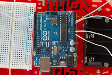
Here is the Arduino board with the cables in place, before I inserted the motor shield:
And here it is with the motor shield in place:

Once the motor shield went in the cables could not be removed, so this solution will likely hold until I can get a better alternative. Unfortunately I only had white cable, as I would have preferred to use colored cables to make it more clear what each cable was and, why not say it, to make the robot a bit more colorful. Oh, well...
The last step in building the robot was to make all the connections, so I started by inserting the distance sensor and the bluetooth slave in the breadboard.
The white cables from the 5V and GND pins went into red and blue pins in the breadboard. Then using red and blue jumper cables I extended the power to the proper pins in the distance sensor and bluetooth slave.
The white cables coming out of analog pins 0 and 1 went to pins Trig and Echo in the distance sensor, and the ones from digital pins 0 and 1 went to the bluetooth slave.
Finally, I attached the red and black cables from the two motors that came with the vehicle kit to motor inputs M1 and M3 in the motor shield.
If you don't understand these connections check out the previous article, where I included connection diagrams and explained in detail how these hardware components work.
Testing
Right after I completed the assembly of the robot I wanted to make sure the connections were working.
So what I did is simple. I uploaded the three sketches from the previous article that control the distance sensor, the motors and the bluetooth slave one by one to test each component individually.
As I mentioned in the previous article, when the bluetooth slave is connected to the serial pins in the Arduino board the serial communication with the computer to upload sketches does not work very well, so each time I needed to upload a new sketch I unplugged the red power cable that goes to the bluetooth device to make sure there was no interference.
In the end I verified that all the components worked fine, so I called the hardware assembly phase complete!
Introducing... the Michelino!
Without further ado, let me introduce you to my completed robot, which I have named Michelino (pronounced mi-keh-lee-no):


Final words
My robot hardware is complete, now I need to give it its brains.
In the next few articles I will write the robot software in C++. This is no small task, as I will be writing the software from scratch. As a side note, I plan to release the code as open source for others to learn from, enjoy or improve.
Stay tuned, as this is bound to get interesting pretty soon!
Miguel
Become a Patron!
Hello, and thank you for visiting my blog! If you enjoyed this article, please consider supporting my work on this blog on Patreon!

-
#26 Miguel Grinberg said
@aahd: are you sure the new sketch uploaded to the Arduino? Chances are you are still running the old sketch that uses the distance sensor.
-
#27 Brandon Carmona said
Hey, I was wandering if you can also install a arduino UART/ SIP JPEG Camera and shield. So that you can use this robot as a spying or security robot.
-
#28 Miguel Grinberg said
@Brandon: Sure, I don't see any problems with that, other than having to use more power.
-
#29 Muhammad said
thanks
-
#30 Robert kearbey said
Hi Miguel
I am well on my way building the robot. Just got Bluetooth board JY-MCU V1.06.
Question: I have only IOS phones laptop etc. I just read something that it will only work with android. Is that correct and if so, is there another solution. BTW I love the way you present your blogs. Even I can understand. Bob -
#31 Miguel Grinberg said
@Robert: I don't use iOS devices, but I'm pretty sure you can make them work too. It's just a matter of finding an app that can control your robot. The commands are probably going to be different, so you will need to modify the code to work with the remote control app that you use.
-
#32 Zeno said
What about power? Should I power the motor shield and the arduino separately?
The motors support a maximum of 6V, but arduino requires at least 7V. -
#33 Miguel Grinberg said
@Zeno: it really depends on the hardware that you are using. Using a separate power source for the motors is usually a good idea, but you may get away with a single power source in some cases.