Building an Arduino Robot, Part II: Programming the Arduino
Posted by
on under
Welcome to the second article in the tutorial series in which I'm building a remote controlled Arduino based vehicle robot.
Here is the list of articles I have published:
- Part I: Hardware Components
- Part II: Programming the Arduino (this article)
- Part III: Assembling the Robot
- Part IV: A (Not So) Basic Robot Firmware
- Part V: Avoiding Obstacles
- Part VI: Remote Control
In the previous article I introduced you to my project. I showed you the parts I bought and what features I wanted to implement in my little remote controlled robot vehicle.
Today I will introduce you to the programming side of my project. This is a pretty long article that is heavy in information that can be applied to most Arduino projects. By the end of it you will know the basics of programming sensors, motors and other devices connected to the Arduino, and will also have an understanding of how a wireless remote controller can communicate with the Arduino board over Bluetooth. I encourage you to get the parts I listed in the previous article and try these tests along with me.
The Arduino Pins
The Arduino board communicates with connected devices via its input and output pins, so I'll quickly go over what these pins are.
Here is a diagram of a typical Arduino board.

On the left side you have the USB port (grey box) and the power input jack (black box). During testing I will be powering my Arduino with a USB cable, but the final robot will receive power from a battery box connected to the power input jack.
On the top, from right to left there are 14 pins labeled 0 to 13. These are the digital pins. These pins can be individually configured as inputs or outputs, meaning that digital data can be read or written from connected devices on these pins. Since these pins are digital, they have only two possible states, HIGH and LOW.
Some of the digital pins have preassigned functions. Pins 0 and 1 are also labeld RX and TX respectively. These are used by the serial communication hardware to send and receive data. Pin 13 has a LED attached to it on most Arduino boards, so it is a convenient pin to send simple visual information out to the real world. The pin 13 LED is located below the pin 13 itself, labeled with the letter L in the diagram above. Pins 3, 5, 6, 9, 10 and 11 are marked with a ~ or a PWM label, short for pulse width modulation. These pins are capable of producing simulated analog output over a digital line. These can be used, for example, to light a LED at different levels of intensity.
The next pin on the top from right to left is GND, short for ground. The ground is what closes a circuit and allows the electric current to flow uninterrupted. Connected devices can connect their own GND pin here.
The next pin on the top left is labeled AREF, short for analog reference. This pin is rarely used, it tells the Arduino how to configure the voltage range of the analog pins.
Some Arduino boards have more pins to the left of AREF. Since these are not in all boards I will not discuss them here.
On the bottom right we have six pins labeled 0 to 5. These are the analog input pins. Unlike the digital pins which have only two possible states, an analog pin can have 1024 possible states, according to the voltage applied to it. Typically the voltage range goes up to 5V, but the range can be changed by applying the desired maximum voltage to the AREF pin. Also unlike the digital pins which can be configured as inputs or outputs, the analog pins can only be inputs.
An interesting property of the analog pins is that they can be used as digital pins as well, with pin numbers 14 to 19. You will see later that an important part of any project is allocating pins to components. If you are running short of digital pins keep in mind that you have six more available to you.
Continuing on the bottom from right to left we find a pin labeled VIN. This pin provides direct access to the voltage provided by the power supply. So for example, if you power your Arduino with a 9V power supply through the power jack, then this pin gives you 9V.
The next two pins are labeled GND and are two more ground pins, exactly like the one in the top row. They are here just for convenience.
The next two pins are labeled 5V and 3.3V and just return those voltages, regardless of what the voltage of the power supply is.
Next we have the RESET pin. When this pin is connected to GND the board will reset. So this is a handy pin to build an external reset button.
As with the top row of pins, some boards have a more pins on the bottom left that I will not cover here. If you are interested in finding out what extra pins in your board do you should consult the documentation for your board.
Programming the Arduino with Sketches
By now you are probably wondering how can you make the Arduino do things.
The easiest way to program the board is with the Arduino software, which is free and open source, and available for Windows, Mac OS X and Linux users.
Here is a screenshot of the Arduino software:

The white area is where the program is written. The programming language that the Arduino platform uses is called C++ (pronounced see plus plus), a language that is regarded as very powerful but difficult to learn. I will try to explain the basics of C++ in this and the following articles, but I will not cover C++ programming in detail. If you have any specific C++ programming questions I'll be happy to address them in the comments at the bottom.
C++ programs are written as regular text. Arduino calls these programs Sketches. Then a utility called compiler reads the sketch and converts it to machine instructions that the Arduino understands.
The black area at the bottom of the Arduino software window is where status information appears. For example, if your C++ code has an error this is where you will see the details.
The Arduino software also has a toolbar, with the following buttons (in order, from left to right):
- Verify: Runs the C++ compiler on your program. If there are any errors you will see them in the black status area.
- Upload: Compiles your C++ program like the Verify button does, and if compilation is successful it uploads the resulting program to the Arduino board, which must be connected to the computer through the USB port.
- New: Clears the program currently loaded.
- Open: Shows a dropdown with a long list of example programs to load or the option to load a sketch from disk.
- Save: Saves the current program to a file on disk.
- Serial Monitor: Opens the serial monitor console. This is used mostly for debugging, as I will show in a little bit.
"Hello, world!", Arduino style
To begin, let's write a very simple program that writes a message to the serial port. We will see this message in the Serial Monitor.
I assume you will be doing this with me, so please follow along.
First install the Arduino software. Installation instructions are very simple, you should not have any trouble with this step.
Start the Arduino software making sure the Arduino board is not connected to your computer. Open the Tools menu, then the Port submenu. Take note of the options that appear here and then close the Arduino software.
Next connect your Arduino board to your computer using the USB cable. If you are doing this on Windows, then see this page for instructions on how to install the Arduino board drivers. If you are on Windows 8, also see this page for information on how to bypass the requirement for signed drivers. Mac and Linux users are lucky and do not need to install any drivers.
With the Arduino board connected, launch the Arduino software again. In the Tools menu open the Board submenu and make sure the correct model of Arduino board is selected. Then in the Port submenu find the serial port entry that did not appear in the list when you had the Arduino board disconnected. That's the serial port that is assigned to the Arduino connection, so select that one.
Then in the white area type (or copy/paste) the following C++ program:
void setup()
{
    Serial.begin(9600);
}

void loop()
{
    Serial.println("Hello, world!");
    delay(1000);
}
Press the Upload button to compile and upload the sketch to the board. If you made any mistakes they will be indicated in the black status area. At this point the errors will look very cryptic if you are not used to programming in C++, so the best you can do is compare what you typed against the above and fix any differences you find until the upload operation succeeds.
If the Upload is successful the status area will show a message similar to the following:
Binary sketch size: 1,978 bytes (of a 32,256 byte maximum)
At this point the program is running inside the Arduino. You will notice that the LED labeled TX blinks every once in a while, indicating the Arduino board is transmitting data through the serial port.
To see the data click on the Serial Monitor button in the toolbar. At the bottom right of the serial monitor window make sure the drop-down is set to 9600 baud. You should now see the message Hello, world! printing in the window every second.
Congratulations, you've completed your first Arduino sketch!
I'm sure you want to understand a little bit how this sketch works, so let me give you some information.
Arduino sketches have two main functions, called setup and loop. When the program starts it will execute the setup function. This function is supposed to initialize the hardware and get it ready for operation. Then the loop function will be called repeatedly until the Arduino is reset or powered off. If you look at the code above you will see these two functions, each starting with the word void followed by the function name, and ending with a closing curly bracket.
What goes before the opening curly bracket is called the declaration of the function. What goes in between the opening and closing curly brackets is the actual code of the function, or in other words, the instructions that the Arduino executes when the function is invoked.
In this small example the setup function initializes the serial interface by calling the Serial.begin function. What goes in between the parenthesis are called arguments, and each function defines what arguments it needs, if any. The Serial.begin function requires the speed of the serial communication to be given as an argument, in baud units. I selected 9600 bauds in this example. The statement ends with a semicolon, this acts as a statement separator.
Now how do you know what functions you can use in your sketches?
That's what the Arduino reference is for. This page has a quick reference for C++ and the list of all the functions that are provided by the Arduino development environment.
For example, let's say you want to know all the functions related to serial port communications. Then you can open the Serial link under the Communications section. You will find the begin function I used above listed there. Note that outside of any context the function is called Serial.begin, but when the context is clearly in the Serial class, then it is enough to call the function begin. If you now wanted to see information about the arguments required by the Serial.begin function you just click on it to go to the Serial.begin documentation.
The Arduino reference documentation is very good so I recommend you keep it open in a browser window at all times when you are writing sketches.
Let's go back to our example. The second function is the loop function. This function makes two function calls. First it calls Serial.println, passing the message "Hello, World!" as an argument. As you can guess, the Serial.println function prints a message to the serial port. The message is given as a character string, within double quotes. The function is called println and not print because in addition to printing our message it ends the line, meaning that the next print will start at the beginning of the next line. There is, in fact, a print function that prints the message and does not move to the next line.
The second and last instruction in the loop function is a call to a function called delay. This function pauses the program for the amount of time specified as an argument. The units of time are given as milliseconds, so I'm passing the value 1000 to pause the program for one second.
Since the loop function is invoked repeatedly, the result of this program is that the text Hello, world! is printed to the Serial Monitor every second.
Working with LEDs
Let's look at an improved version of the previous sketch:
void setup() {
    Serial.begin(9600);
    pinMode(13, OUTPUT);
}

void loop() {
    Serial.println("Hello, world!");
    digitalWrite(13, HIGH);
    delay(500);
    digitalWrite(13, LOW);
    delay(500);
}
Enter the code above in the code window of the Arduino software replacing the old sketch and upload it to your board to test it.
If you understood the first sketch then you can probably figure out what this version does easily.
In the setup function in addition to initializing the serial port like before I'm also initializing pin 13 as an output pin. Recall that digital pins can be used as inputs or outputs, so whenever you need to use a pin you have to configure it for the intended use. In this case I'm making it an output pin, which means that I can write a value to this pin, and the value I write will affect the electrical current coming out it. See the pinMode documentation for details on this.
The loop function prints the message to the serial port like before, but then sets pin 13 to a HIGH state with the digitalWrite function. In most Arduino boards this lights the on-board LED. Then the program pauses for 500 milliseconds, or half a second. Then the state of pin 13 is changed to LOW to turn the LED off. Then the program sleeps for another half a second.
The loop function is called over and over again, so what the above code does is make the LED blink! It blinks at a rate of one blink per second, staying on for the first half second, then off for the other half.
Programming the Distance Sensor
Now you know how to do the basic stuff that appears in every Arduino introductory tutorial. Are you ready to do something real with your Arduino? I hope you are!
I'm going to show you how to program the HC-SR04 distance sensor. Recall that I will be using this sensor to help my robot "see" and avoid walls and obstacles.
For most devices that connect to the Arduino board there are already appropriate libraries of functions incorporated into the Arduino software. You can see what libraries are included by going to the Sketch menu, "Import Library..." submenu. You will see libraries there for motors, LCDs and a variety of other devices.
Unfortunately there is nothing for distance sensors. So how can one control such a device?
In most cases manufacturers of Arduino compatible devices provide the required libraries to control their products. Other times developers write their own libraries and make them available as open source. The documentation of the device is the first place to go, but as always in cases like this, Google is your best friend.
Searching around I've found not one but three open source Arduino libraries for my distance sensor, here, here and here. I quickly reviewed them and out of the three the arduino-new-ping library appeared to be the most complete, so I decided to give that one a try first. If that one does not work I can always go get one of the other two.
The library comes in a zip file, available as a download link in the page linked above. To install it and make it available in the Arduino software you just need to unzip it and copy the top folder (called NewPing) inside the libraries folder in your Arduino sketches folder. The Arduino sketches folder is in your home directory, see the documentation for details.
After you install the NewPing library close and reopen the Arduino software so that it can recognize it.
Now start a new sketch, go to the Sketch menu and select "Import Library...". You should now see NewPing in the list. If you select this library the following line will be added to your sketch:
#include <NewPing.h>
This is telling the C++ compiler that you will be using the functions from the NewPing third party library. Note that you don't have to go through the menus to get this text written for you, if you prefer you can write it yourself.
Before I show you the sketch that controls the distance sensor take a look at the following wiring diagram:
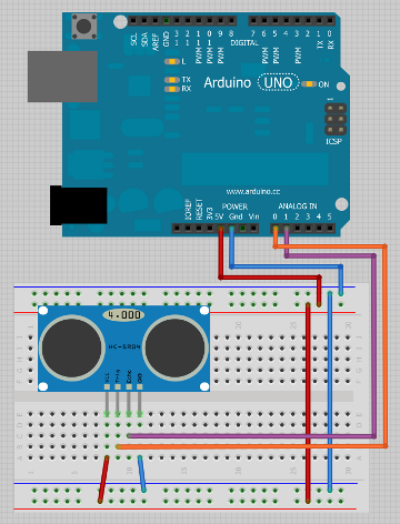
As you see in the diagram I'm using the breadboard and some jumper cables to make all the connections.
First I connected the 5V output from the Arduino to the "red" side of the top section of the breadboard, and the GND line to the "blue" side. The top and bottom sections of the breadboard have "red" and "blue" sides, and these are typically used to distribute power and ground lines to the whole breadboard. Plugging the 5V output to one of the red pins makes the 5V available to all the red pins in that row, and likewise, connecting GND to a blue pin makes GND available in all the blue pins in the row.
Next I transferred the 5V and GND lines to the bottom part of the breadboard with two more jumper cables. This is always a good practice when prototyping, setting up the breadboard like this ensures that you can always grab your power and ground lines from the side that is most convenient.
The distance sensor plugs nicely into four consecutive pins in the middle of the breadboard. The two middle sections of the breadboard connect groups of five vertically aligned pins together, so to make a connection to one of the sensor pins I just plug one end of the jumper cable into any of the remaining four pins in the same group.
The leftmost pin is labeled VCC, this is the pin that should be connected to the 5V line. So to do that I connect a jumper cable to this pin from the sensor to one of the red pins in the breadboard bottom. The next two pins are labeled Trig and Echo. These connect to any two available pins in the Arduino board. Since any pins will do, I will be using analog pins 0 and 1, which as I said before can double up as digital pins 14 and 15. The rightmost pin is labeled GND, so the connection can go to any of the blue pins at the top or bottom of the breadboard.
Here is an actual picture of how this circuit looks in real life:

So far it's been pretty easy, right?
Let's see what the sketch looks like:
#include <NewPing.h>

#define TRIGGER_PIN  14
#define ECHO_PIN     15
#define MAX_DISTANCE 200

NewPing DistanceSensor(TRIGGER_PIN, ECHO_PIN, MAX_DISTANCE);

void setup()
{
    Serial.begin(9600);
}

void loop()
{
    unsigned int cm = DistanceSensor.ping_cm();
    Serial.print("Distance: ");
    Serial.print(cm);
    Serial.println("cm");
    delay(1000);
}
There are a couple new things in this sketch that I haven't used in the previous ones, but overall things are largely similar.
The #include statement at the top tells the C++ compiler that I will be using a third party library. The NewPing.h between the angle brackets refers to a header file that is inside this library. This file contains the definitions for all the functions provided by the library. If a library does not have documentation, chances are there is information at the top of this file.
Next there are a few #define lines. If you recall the LED blinking sketch from above, I have written the pin number 13 in a couple of places there. Instead of using the number directly I could have defined a constant. That's what #define does. You use it to give a value a meaningful name, then in the rest of the sketch you can write the name instead of the value. This is useful to make the code more readable, but also makes it very easy to change the pin assignments, because then you just go to the top of the sketch and update the numbers in just one place.
In this sketch we have three #define statements. The first two create constants for the Trig and Echo pins of the distance sensor which I connected to pins 14 and 15 respectively (analog pins 0 and 1). The third #define is to set a constant for the maximum distance that I want the sensor to recognize, which I set to 2 meters, using centimeter units.
Next we have the following statement:
NewPing DistanceSensor(TRIGGER_PIN, ECHO_PIN, MAX_DISTANCE);
This statement creates an object that represents the distance sensor. The syntax for object creation requires the class of the object first (NewPing in this case), then the name I want to give the object (DistanceSensor) and then any arguments enclosed in parenthesis. The arguments that the NewPing object requires are the trigger pin, the echo pin and the maximum distance to consider, all in that order and separated with commas. These happen to be the three constants defined above, so I can write the names instead of the values.
Note that the object is created outside of any functions. Objects can exist only at the level they are created, so creating the object inside the loop function would make it disappear when that function ends. The next time loop is called a new object would be created and initialized, which would be a waste of time and effort. Putting the object creation outside of any functions makes it a global object that persists across function calls.
The setup function is exactly like the one I used before, it just sets up the serial communication so that we can see output from the Arduino board in the Serial Monitor.
The loop function starts with a type of instruction that I haven't used before:
unsigned int cm = DistanceSensor.ping_cm();
Let's analyze this statement one piece at a time. To the right of the = sign I am invoking a function called ping_cm provided by the DistanceSensor object created above. This function is slightly different than functions I used before, because in addition to doing something it returns a result, which in this case is the distance to the closest object measured in centimeters.
Since I intend to use this distance result later in the sketch I have to store it somewhere, so to the left of the = sign I have created a variable, which is basically a space in memory where a value can be stored. The C++ syntax for variable creation requires me to provide the type of values this variable will store first (unsigned int in this case, a positive integer) and then the variable name, which is any name of my choosing that I will use later to refer to the value stored in the variable.
As a side note, the distance sensor library documentation indicates that there is also a ping_in function that is equivalent to ping_cm but returns the distance result in inches. Another option provided by the library is a function ping, which just returns the time it took the ultrasonic signal to make a round trip back to the sensor in microseconds. You can then divide this time by the time it takes sound to travel twice the distance units of your choice to get the distance in those units. For my purposes having the distance in centimeters is accurate enough.
Next in the loop function I have three consecutive prints to the serial port. The first two prints use the Serial.print function and the last uses Serial.println. That means that the second and third prints will go to the same line as the first, and after the third message is printed the cursor will move to the next line.
The first and last print statements print text messages like in the previous sketches. The middle print, however, prints the cm variable, in which I have the result of the distance sensor ping_cm function.
The final line in the loop function does a delay of one second, exactly like before.
When you run this sketch on your board and move your hand or some other object closer and farther away from the sensor you will see something like this in the serial monitor:
Distance: 28cm
Distance: 28cm
Distance: 21cm
Distance: 18cm
Distance: 15cm
Distance: 15cm
Distance: 12cm
Distance: 12cm
Distance: 24cm
Fun with motors
Let's move on to something else. The vehicle kit that I'm using for my project comes with two wheels, each with an attached motor.
The motor driver board that I have is the Adafruit Motor Shield, which comes with its own library, called AF_Motor. If you are using the same motor controller then go ahead and install this library in your Arduino environment. If you are using a different motor controller then you'll have to find the library that works for your hardware.
Most motor controllers come as a shield, which means that the motor board plugs right on top of the Arduino board, connecting to both rows of pins, even though many of the pins are not used to control motors. The nicer motor shields provide pass-thru headers with access to all the Arduino pins. Unfortunately the Adafruit shield does not give access to the pins, so connecting additional components becomes difficult. This is a problem I'll have to work around.
The Adafruit motor controller can drive up to four DC motors, labeled M1 through M4 in the board. I need just two, so for convenience I'm going to connect my two motors one on each side of the board, using the M1 and M3 connectors.
To test the motors on the assembled kit I turned it upside down, so that I can see the wheels turn without the vehicle moving while the Arduino is connected to the USB power. The motor connections are extremely simple, each motor has just two connections:

The Arduino board is hidden underneath the motor shield in this picture.
Here is the sketch that I used to test the motors:
#include <AFMotor.h>

AF_DCMotor Motor1(1);
AF_DCMotor Motor2(3);

void setup()
{
}

void loop()
{
    Motor1.setSpeed(255);
    Motor2.setSpeed(255);
    Motor1.run(FORWARD);
    Motor2.run(FORWARD);
    delay(1000);
    Motor1.run(BACKWARD);
    Motor2.run(BACKWARD);
    delay(1000);
    Motor1.run(FORWARD);
    Motor2.run(BACKWARD);
    delay(1000);
    Motor1.run(BACKWARD);
    Motor2.run(FORWARD);
    delay(1000);
    Motor1.setSpeed(0);
    Motor2.setSpeed(0);
    Motor1.run(BRAKE);
    Motor2.run(BRAKE);
    delay(1000);
}
I don't think I need to explain every line in this sketch, since it does not have any new C++ constructs. Like the distance sensor, each motor requires an object to be created, this time one of class AF_DCMotor. The only argument is the motor number, from 1 to 4. I created two motors, numbers 1 and 3 to match the motors connected to ports M1 and M3 of the controller.
The motors are controlled with two functions, setSpeed and run. The setSpeed function takes a numeric argument with range 0 to 255, indicating the speed the motor should turn. The run function configures the mode in which the motor runs, which can be FORWARD, BACKWARD, BRAKE or RELEASE.
The sketch above makes the wheels do a few tricks: one second of both wheels going forward, then one second of both wheels going backwards, then one wheel forward and the other backwards, then each wheel reverses direction, then the wheels stop for a second. Then the cycle repeats with the next invocation of the loop function.
Remote Control over Bluetooth
The final piece of hardware that I intend to use in my Android robot vehicle is the Bluetooth slave, which connects to my smartphone to receive remote control commands.
I expected bluetooth communication would be the most complex aspect of my project, but after reading the one page documentation that came with my device I was proved wrong. Turns out the bluetooth slave works over the standard serial communication protocols in the Arduino board, which means you use the functions in the Serial class like I used in all the previous sketches. When the Arduino board with Bluetooth is paired with a smartphone a Serial.print command will send the data not to the PC but to the phone! The Serial class also has functions to read data from the other end, so I will use these functions to receive commands from the smartphone.
The wiring of the bluetooth slave is pretty simple:

Note how the RX and TX pins in the Bluetooth slave go to digital pins 0 and 1 respectively, the pins that are dedicated to serial communications.
This is how my actual circuit looks like with everything connected, noting that in the picture below the Bluetooth dongle is facing the other side, so the connections appear reversed from the diagram above:

An example sketch that allows remote communication is below:
void setup()
{
    Serial.begin(9600);
    pinMode(13, OUTPUT);
}

void loop()
{
    if (Serial.available() > 0) {
        char ch = Serial.read();
        Serial.print("Received: ");
        Serial.println(ch);
        if (ch == 'a') {
            digitalWrite(13, HIGH);
        }
        else {
            digitalWrite(13, LOW);
        }
    }
}
The setup function does not have anything I haven't done before. From reading it you can guess that I'm going to be playing with the pin 13 LED again.
In the loop function I'm introducing a new type of C++ statement, the if statement, sometimes also called conditional. A conditional is useful when you want the program to do something only when a condition is true.
What follows after the if keyword is the condition, enclosed in parenthesis. In my sketch the condition that I'm checking is Serial.available() > 0. To know if this condition is true or not the Arduino will invoke the function Serial.available, which returns the number of data bytes that have been received in the serial port, and compare that number against 0. If the number of available bytes is greater than 0 then the condition is true, so the instructions that are between the opening and closing curly brackets will be executed. If the condition is not true, then the whole group of instructions inside the curly brackets will be skipped.
Do you understand why a conditional makes sense in this case? The Serial.available function will return a positive number only when the master on the other end of the serial communication has sent data. Saying if Serial.available() > 0 in C++ is the same as saying "if there is data available" in English. If the condition is not true (which is the same as saying it is false), then it means that at that moment the remote controller has not sent any data, so in that case I have nothing to do and skip the whole thing.
So what happens when the condition is true?
The very first thing I do inside the if block is read a byte from the serial port, using the Serial.read function. Note that I use a variable to store the result, but this time I declared the variable with the type char, which in C++ is the type that represents one byte of data.
Once I have my byte of data I print it, using our old friends the print and println functions.
After I print the data received I have another conditional (note how I indent my sketch to make it very clear that I have one if statement inside another). This time my condition is ch == 'a', which as I'm sure you guessed, will be true only when the lower case letter a is the data received. In that case I set pin 13 to HIGH, which turns the LED on.
The else statement that follows is an extension to the if. I said before that when the if condition is false the instructions inside the curly brackets are skipped. When a conditional has both if and else blocks the condition determines which of the two blocks executes. If the condition is true the block that follows the if executes and the block that follows the else is skipped. If the condition is false the block that follows the if is skipped and the block that follows the else executes.
Do you see what this conditional does, then? When the Arduino receives an a it will turn on the pin 13 LED. Any other data received will turn it off. With this simple sketch I built a remote control for the LED in the Arduino board!
When trying to upload this sketch to my Arduino I've found that often the upload failed. I believe this is a result of a collision between the serial communication established by the computer and the one from the Bluetooth slave. It appears that the Bluetooth slave wins and prevents the computer from talking to the Arduino. I have found that disconnecting the RX and TX pins from the Bluetooth slave when I need to upload a new sketch solves the issue.
Are you ready to try this?
Go ahead and install BlueTerm in your Android device. This app works exactly like the Serial Monitor from the Arduino software. I suppose there is an equivalent app for iOS, if you have found one that works please let me know in the comments below.
Update: It appears that nBlueTerm is an equivalent application for iOS devices, though I haven't had a chance to test it yet.
If you don't have a smartphone or the Bluetooth slave you can try this sketch using the serial communication to the computer and the Serial Monitor.
Once you have the app in your Android device and the sketch uploaded to the Arduino you are ready to go. Start by powering up the Arduino (via USB cable or power supply). The red LED in the Bluetooth slave will blink rapidly, indicating it is ready to pair with another device. Start BlueTerm in your smartphone and select "Connect Device" from the menu. The Bluetooth pairing window should appear and should show a device with name linvor. Select this device to establish a connection. Use 1234 as pairing code.
Once the connection is established the LED in the Bluetooth slave goes steady, and on the smartphone you have a terminal like the one in the Serial Monitor. Any letters that you type are sent over to the Arduino, and the Arduino responds back with a message that confirms that it has received the same letter. When you type the lower case letter a in addition to the above the LED in the Arduino board lights up. When you press any other key the LED goes off. Pretty cool, right?
Final words
I hope you found the information in this article useful. Please let me know if you have any questions below in the comments.
In the next article I'll be discussing a much lighter topic. I will show you how I mounted and connected all the hardware into the vehicle kit platform. Then after that I 'll show you how I developed the firmware for my robot from scratch!
As always, I thank you for being a loyal reader. I hope to see you next time!
Miguel
Become a Patron!
Hello, and thank you for visiting my blog! If you enjoyed this article, please consider supporting my work on this blog on Patreon!

-
#1 F.Javier Fernandez said
Very nice series of articles, clear explanation evev for beginners .
Equivalent Bluetooth applivation for IOS is nBlueTerm, available free @ Appstore.
-
#2 Miguel Grinberg said
@F.Javier: thanks for the tip!
-
#3 Markus said
Hi Miguel
Your guideline is verry helpful for me
Im lookong forward for the next PartRegards
Markus -
#4 Dimitri said
Such a detailed explanation! Thanks for spending your time on this project.
-
#5 salem said
i cant believe that they are guys like you , who want to share their projects for free , what can i say . thank you thank you
-
#6 Bas15 said
Thanks a lot
It is wonderful, -
#7 Chaminda Amarasinghe said
Hi Miguel,
Thanks. Very nice article
-
#8 Kevin said
Hi - You recommend the Arduino Motor Shield R3, though, you article uses the Adafruit. I would like to use the Arduino MS R3 - can I use the AFMotor library?
Thanks. -
#9 Miguel Grinberg said
@Kevin: Unfortunately the Adafruit motor shield is different than the Arduino one. To use the Arduino R3 shield you will need to write different code to control the motors, and you will not use the AFMotor library. The changes should be pretty simple though.
-
#10 sid said
I am using arduino motor shield r3 and have written a code for the same with bluetooth module but i want to use ping sensor code also with it.I am totally new to this.how can i power both ping sensor and bluetooth from motor shield and how to write another program along with my motor shield and bluetooth code.
-
#11 Miguel Grinberg said
@sid: All the peripherals are powered from the Arduino. See the wiring diagrams above in this article. As for using all the components together, see the tutorials that follow this one for some ideas.
-
#12 Marcos Montelpare said
he construido un robot como est siguiendo paso a paso el tutorial con un arduino Uno R2 + el escudo motor Adafuit + Bluetooth master/slave + pingHCSRO4. Luego de leer todos los tutoriales descargue el archivo Michelino y al copiarlo en el compilador el verificador detecta un error aquí
private:
Motor leftMotor;
Motor rightMotor;
como estoy comenzando con esto no he podido corregirlo. agradecería su ayuda para poder probar todo el sistema -
#13 Nilesh said
Hi Miguel. Thank you for the prompt response. After a little bit of research I found this tutorial for programming Arduino Motor Shield http://www.instructables.com/id/Arduino-Motor-Shield-Tutorial/step5/Two-Motors/.
How would you suggest to use this? Shall I create a library file from this and include it in my sketch ?
-
#14 Miguel Grinberg said
@Nilesh: you can create a new driver that uses the same functions of mine. If you do it that way the rest of the program will not know the difference.
-
#15 Gabriel said
how can i control the robot from ios? if so, what app can i use
-Gabriel
-
#16 Miguel Grinberg said
@Gabriel: I don't use iOS myself, so I can't recommend anything. You should look for a bluetooth remote control app for robots.
-
#17 Mick said
Following your tuition I hit problems had to solder adafruit motor shield I managed to get two dc motors running using M2 and M3. Motor 2 has racing faster thank M3 set the speed lower in M2 to little effect so I stopped both motors speed set to zero , but power was still being delivered to both motors. Do you know of any way tho resove this problem ?
-
#18 Miguel Grinberg said
@Mick: If the motors run at different speeds you may need to calibrate them. You can do this by trial and error. For example, you may find that you need to set the faster motor to 90% of the speed of the slower one and then they match.
-
#19 Chip said
When I figured out you can use the other pins, I just removed the L293N chips from the Motor Shield and wired them up directly
-
#20 Marcel said
Thank you for a such great tutorial! I have a question related to this project: what pins are conected between motor shield and arduino? I had studied the code, but i can't see what pins from arduino are connected to the shield. I don't have a motor shield and i will try to use a diver circuit + a shift register from schematics of adafruit motor shield v 1.2, and this information is the missing piece to aquaire this. Thank you and keep working to new projects!
-
#21 Miguel Grinberg said
@Marcel: The FAQ page for the Adafruit motor shield describes the pins that are in use.
-
#22 Marcel said
Thank you very much!
-
#23 Nilesh said
I just found out that nBlueTerm app for iPhone does not work with BT2S bluetooth slave. I have tested it as well I have got the confirmation from Virtuabotix as well. The reason being iPhone does not allow serial connection easily (nearly impossible). Only option as of now is to either use and Android device or use the new BTLE shield specially made for bluetooth connection with iPhone.
-
#24 Subhash Jadhav` said
I use the Ultrasonic range finder sensor instead of distance sensor.. There are 3 pins in this sensor 1 of them Positive 2 of Negative & 3 of Analog pin.. then how to make the code ? I build 4wd obstacle avoidance robot. I use Arduino uno r3 board,Adafruit motor shield,4 Bo gear motors,1 gm servo,& the distance sensor. I don't understand how to make the code for this robot. pl help....
-
#25 Miguel Grinberg said
@Subhash: The NewPing library probably supports your ultrasonic range finder. Did you try it?