Building an Arduino Robot, Part VI: Remote Control
Posted by
on under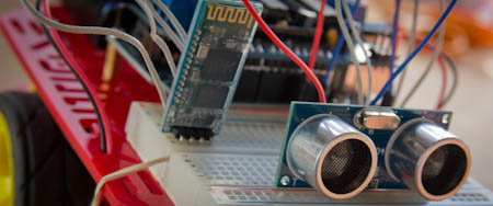
Welcome to the sixth article in the tutorial series in which I'm building a remote controlled Arduino based vehicle robot.
Here is the list of articles I have published so far:
- Part I: Hardware Components
- Part II: Programming the Arduino
- Part III: Assembling the Robot
- Part IV: A (Not So) Basic Robot Firmware
- Part V: Avoiding Obstacles
- Part VI: Remote Control (this article)
In the past two articles I have implemented the motor and distance sensor control for my little robot vehicle, using sound software development techniques that make this project easier to write and to maintain.
Today I will be implementing the most challenging (and let's admit it, also the most fun) aspect of my project: the ability to remotely control the robot from a smartphone over Bluetooth.
A small improvement
Before I get into the main topic of this article I'm going to tell you about a small modification I've made to my robot that helps with the remote control functionality.
If you recall the article in which I showed you how to program the Bluetooth module, it is not possible to upload a sketch over USB while the Bluetooth module is connected to pins 0 and 1, because those pins are used by the USB/serial communication.
When I started writing the remote control code I became a bit frustrated with having to constantly connect and disconnect Bluetooth and USB. To avoid this hassle I decided to use the SoftwareSerial.h library that comes with the Arduino software to move the Bluetooth connection to a different set of pins.
The change is pretty simple. I moved the connections from the Bluetooth module going into pins 0 and 1 to analog pins 2 and 3 (numbered 16 and 17), which are unused. Then I created a SoftwareSerial object at the top of the sketch:
#define BT_RX_PIN 16
#define BT_TX_PIN 17

#include <SoftwareSerial.h>
SoftwareSerial BTSerial(BT_RX_PIN, BT_TX_PIN);
And then, instead of using the Serial object like in my previous tests, I used the BTSerial object. The setup() in my sketch then changed to:
void setup()
{
    Serial.begin(9600);
    BTSerial.begin(9600);
}
Why keep the Serial.begin() call? Because I elected to keep sending the logging output to the regular serial interface. I now have access to two serial ports, so I will use the Bluetooth connection for remote commands and the USB one for logging and debugging output. Neat!
With the Bluetooth module connected in this way there is no collision with the USB serial interface so I could keep the USB cable connected at all times while developing and testing.
Remote Control device driver
Like in the previous articles, I'm going to start by designing a device driver that can abstract the main sketch from having to deal directly with hardware.
But this case is a little different. We really have two separate pieces to abstract. The most obvious is the communication method. My robot uses Bluetooth, but this is not the only mechanism by which a robot can be controlled. At least I can think of three more, WiFi, RF and infrared. I clearly need a device driver that can read remote commands, regardless of the wireless technology used.
The second, and less obvious dimension to this problem is the remote protocol. Different remote controllers will use different command codes to mean the same thing. For example, one remote control may send the command to turn left as a byte, maybe the letter "L". Another controller with a numeric keypad configuration may use "4" for the same thing. Another, joystick inspired remote control may not support a direct "go left" command at all and may just send instructions as vectors in a two-dimensional grid, so going left would be given as two numbers, (-1, 0). I do not really want to deal with these differences in the high-level robot code because that will make my code more complex. So clearly a driver that can hide these protocol differences from the main sketch is also needed.
So do I need two different drivers, then? Let's think about how the main sketch will obtain remote control commands. Ideally I want something simple, like a getCommand() function that just returns the next command if one is available. If that's all I need then it seems all the main sketch requires is access to one remote control driver that somehow knows how to receive remote controls and interpret them.
There are two ways this could work. If I implement two drivers, for communication and protocol separately, then the main sketch will only talk to the protocol driver, and it will be the protocol driver's job to know what communication driver to talk to. This provides great flexibility, because the same protocol can easily be supported over different communication channels.
And what would be the alternative? I could embed the communication part inside the protocol driver. This is less flexible because now the remote protocol is tied to a particular communication channel. But on the other side it is simpler to implement because I don't need to define a device driver for communication channels, each protocol driver does its own thing to read remote commands.
Which of these options is better? It really depends. If I was working with standard protocols that remote controls of different kinds implement, then having separate protocol and communication drivers makes sense. In this case, however, I believe the kinds of remote controls that I will find are mostly using proprietary protocols. My impression is that I will never need to use a protocol driver with more than one communication method.
Based on this analysis, I'm going to go with the simpler option for now, one driver for the combined protocol and communication handling. I can always break the driver into two in the future if I find the need.
The remote control driver interface
Given the variety of remote controls out there, I need to find a common format that all the remote drivers can use to represent commands. For the purpose of driving a vehicle, I can think of three types of remote controls that I might ever need to support:
- Keypad based: the robot is controlled with directional keys or buttons.
- Joystick based: the robot is controlled with a multi-directional stick that returns
(X,Y)coordinates inside a circle. - Slider based: the robot is controlled with two sliders, in two possible configurations:
- each slider controls one side of the vehicle
- one slider controls forward/backward motion, the other controls left and right motion.
In all cases it is safe to assume that in addition to the directional control there are a few function buttons.
As you can see there are significant differences between the types of remote controls, so the job of defining a common format for all of them is not easy.
Obviously I cannot indicate direction with simple forward, backward, left and right commands, since many remote controls can provide a finer degree of directional control and it would be a pity to ignore all that extra information.
So I have to pick one of the more advanced remote control data representations. The one that translates more easily into motor instructions for my vehicle is the one where the controller uses two sliders, each controlling one side of the vehicle. This directly translates into speeds for my two motors, so the application can simply send the data from the remote control into the motors. Since I like to keep the main sketch simple this is the approach that I'm going to take.
But there is a downside to selecting a single data representation for all types of controllers. For remote controls that don't use the chosen format a conversion will be needed. To help with this task the base driver class will provide the conversion functions for all types of remote controls.
Let's take a look at the definition of the remote control device driver interface:
/**
 * @file remote_control.h
 * @brief remote control driver definition for the Michelino robot.
 * @author Miguel Grinberg
 */

namespace Michelino
{
    class RemoteControlDriver
    {
    public:
        /**
          * @brief abstract representation of a remote command.
          */
        struct command_t {
            enum key_t { keyNone, keyF1, keyF2, keyF3, keyF4 };
            int left;   /**< left side speed, between -255 and 255. */
            int right;  /**< right side speed, between -255 and 255. */
            key_t key;  /**< function key. */

            command_t() : left(0), right(0), key(keyNone) {}

            // conversion functions
            void goForward();
            void goBack();
            void turnLeft();
            void turnRight();
            void stop();
            void leftAndRightSliders(int l, int r);
            void forwardBackAndLeftRightSliders(int fb, int lf);
            void joystick(int x, int y);
        };

        /**
          * @brief Class constructor.
          */
        RemoteControlDriver() {}

        /**
         * @brief Return the next remote command, if available.
         * @param cmd a reference to a command_t struct where the command
         *   information will be stored.
         * @return true if a remote command is available, false if not.
         */
        virtual bool getRemoteCommand(command_t& cmd) = 0;
    };
};
For this driver I will use an auxiliary struct that represents a remote command. The representation of a command includes left and right slider values and a possible function key. A remote control driver can provide up to four function keys, all listed in the enum definition.
The getRemoteCommand() method will be implemented by remote control drivers. It takes a reference to a command_t structure and is expected to fill it out appropriately, using one of the provided conversion functions if necessary.
As far as conversion functions I know I'm going to need to cover the basic remotes, with four commands to represent the four directions that they provide and one more to make the robot stop. For the more advance remotes I need to handle left and right side sliders (which really require no conversion, but for the sake of abstraction and consistency I will provide a function as well) and forward/back and left/right sliders, which as you will see in a moment also covers the joystick type controllers.
Let's look at the implementation of the conversions:
            void goForward()
            {
                left = right = 255;
            }
            void goBack()
            {
                left = right = -255;
            }
            void turnLeft()
            {
                left = -255;
                right = 255;
            }
            void turnRight()
            {
                left = 255;
                right = -255;
            }
            void stop()
            {
                left = right = 0;
            }
            void leftAndRightSliders(int l, int r)
            {
                left = l;
                right = r;
            }
            void forwardBackAndLeftRightSliders(int fb, int lr)
            {
                left = fb - lr;
                right = fb + lr;
                if (left < -255)
                    left = -255;
                else if (left > 255)
                    left = 255;
                if (right < -255)
                    right = -255;
                else if (right > 255)
                    right = 255;
            }
            void joystick(int x, int y)
            {
                forwardBackAndLeftRightSliders(y, x);
            }
All but one of these are trivial. The first five just set the left and right sides appropriately, while the sixth copies the values given as arguments, since these match the internal data representation.
The next conversion is the one that requires some thought. Here I have a controller that has two sliders, one vertical to move forward or backward and one horizontal to move left or right. Both sliders can be operated independently, so at any given time the remote control provides forward/backward speed and left/right turn values. Somehow I need to use these two values to derive independent left and right values to power the motors.
The algorithm that I came up with for this conversion is relatively simple. The forward/backward slider is transferred directly into both sides, so that when there is no left/right motion the vehicle moves straight forward or backward. Then the value of the left/right slider is added to the right motor and subtracted from the left motor. If the left/right slider is positioned towards the left then it's value will be negative, so adding it to the right side will lower the power of that side, while subtracting it from the left side will make the left side stronger. And these changes will just make the robot go towards the left side, which is what I want. Of course, the reverse happens when the left/right slider is moved towards the right.
The last conversion function is for joystick type controllers. The good news is that I realized that the joystick's (x,y) coordinate values are really the same as the left/right and forward/backward values in the previous conversion functions, so I can use the same function for those.
Remote control driver implementation
My choice of controller is a free Android app called BlueStick. Here is a screenshot of this app:
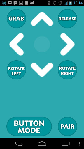
This is a very simple controller with five directional commands and six function buttons. The directional commands can be triggered by touching arrow buttons on the screen or by tilting the phone. The app documentation provides the codes that are sent over Bluetooth for each of the commands:
'0' = Stop
'8' = Up
'2' = Down
'4' = Left
'6' = Right
'A' = Auto Grab
'B' = Auto Release
'C' = Grab
'D' = Release
'E' = Rotate Left
'F' = Rotate Right
Note that while this remote control app gives specific names to its six function keys, I will ignore those names and just define my own meaning for these keys.
The above list defines the protocol for this remote control, so this is really all I need to know to be able to implement this driver. So here is the code for the BlueStick driver:
/**
 * @file bluestick_remote_control.h
 * @brief remote control driver for the BlueStick Android remote control app.
 * @author Miguel Grinberg
 */

#include "remote_control.h"

namespace Michelino
{
    class RemoteControl : public RemoteControlDriver
    {
    public:
        /**
          * @brief Class constructor.
          */
        RemoteControl() : RemoteControlDriver(), lastKey(command_t::keyNone) {}

        virtual bool getRemoteCommand(command_t& cmd)
        {
            cmd.stop();
            cmd.key = command_t::keyNone;

            if (BTSerial.available() <= 0)
                return false; // no commands available
            char ch = BTSerial.read();
            switch (ch) {
                case '8': // up
                    cmd.goForward();
                    break;
                case '2': // down
                    cmd.goBack();
                    break;
                case '4': // left
                    cmd.turnLeft();
                    break;
                case '6': // right
                    cmd.turnRight();
                    break;
                case 'A': // function key #1
                case 'C':
                    cmd.key = command_t::keyF1;
                    break;
                case 'B': // function key #2
                case 'D':
                    cmd.key = command_t::keyF2;
                    break;
                case 'E': // function key #3
                    cmd.key = command_t::keyF3;
                    break;
                case 'F': // function key #4
                    cmd.key = command_t::keyF4;
                    break;
                default:
                    break;
            }
            if (cmd.key != command_t::keyNone && cmd.key == lastKey) {
                // repeated key, ignore it
                return false;
            }
            lastKey = cmd.key;
            return true;
        }

    private:
        command_t::key_t lastKey;
    };
};
If you need a refresher on how the Bluetooth slave module works feel free to reread my previous post about the topic.
This implementation is extremely simple. If the BTSerial class has a character in its queue, then I read it, and depending on what character it is I configure the command, using conversion functions for the directional commands or the key constants for the function keys. I have six function keys in this remote control app, but I decided to just use four in my driver, so I map the two extra keys as duplicates of another two.
I also need to explain what the lastKey member variable is for. As a test I connected the BlueStick app running on my cell phone to a Bluetooth terminal running on another phone, just to confirm that the commands the app sends are in alignment with the documentation. I found that they did match, but also found that the app is constantly sending commands. There isn't really a point in having to handle repeated keys, so I added the lastKey variable to keep track of the last key received. If I find that the new key is the same as the previous one then I just throw it away as a duplicate.
Another important thing to note about this implementation is that it tries to be tolerant of unknown codes. At the start I initialize the command structure as a stop with no function keys. If I receive an unknown character then the sketch will receive a stop command, which will make the robot stop and wait for more commands.
With this basic driver implemented I have enough to incorporate and test the remote control functionality into my sketch, so that's what I'm doing next.
Design the Remote Control Feature
But before I delve into code again, let's discuss how is the robot going to behave, because in the previous article I ended up with a really nice and neat firmware that made the robot run standalone avoiding obstacles, and I'm not really interested in throwing all that code away!
My goal for the remote controlled robot is to incorporate the automated mode I wrote in the previous article as an option that can be enabled with a special remote command. In lack of a better name I'm going to call the automatic mode the "Roomba" mode (I hope I don't get sued for copyright infringement!).
After some consideration I designed the following flow chart for how the robot will operate under remote control:
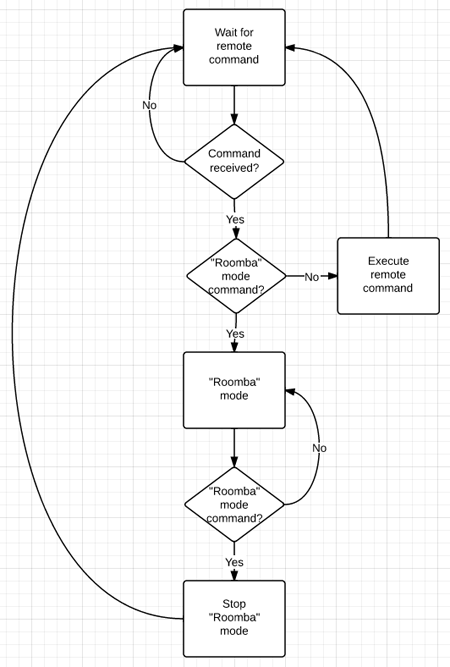
Translating the chart into words this is what I'm going to do:
- The robot will begin by listening for remote commands, without moving.
- If a command is received it will be executed, and then it will go back to listen for more commands.
- There will be a "Roomba" mode command that acts as a toogle.
- Any other commands sent while the robot is in "Roomba" mode will be ignored.
Adding remote control to the sketch
Okay, now I will move on to the most exciting part, which is to actually write the code to make the robot follow the remote commands.
Starting from the sketch as I left it in the previous article I begin by adding the remote control driver class to the top of the sketch, where all the drivers are:
#define ENABLE_BLUESTICK_REMOTE_CONTROL_DRIVER

#ifdef ENABLE_BLUESTICK_REMOTE_CONTROL_DRIVER
#include "bluestick_remote_control.h"
#define REMOTE_CONTROL_INIT
#endif
This class does not take any arguments to initialize, but I can't really be sure other drivers will be the same, so I keep the same style I used in previous drivers and just make the initialization constant empty this time.
Now I can add a remote control object to the Robot class:
private:
    RemoteControl remoteControl;
And I can initialize it in the Robot class constructor:
    Robot()
        : leftMotor(LEFT_MOTOR_INIT), rightMotor(RIGHT_MOTOR_INIT),
          distanceSensor(DISTANCE_SENSOR_INIT),
          distanceAverage(TOO_CLOSE * 10),
          remoteControl(REMOTE_CONTROL_INIT)
    {
        initialize();
    }
I had been using the concept of states to know if the robot was moving or turning. I now need to have an additional state for when the robot is under remote control:
private:
    enum state_t { stateStopped, stateMoving, stateTurning, stateRemote };
And since I have functions stop(), move() and turn() to enable the other states I should be consistent and have one to enter the remote control state:
    void remote()
    {
        leftMotor.setSpeed(0);
        rightMotor.setSpeed(0);
        state = stateRemote;
    }
I also had the tiny functions that returned true if a given state was enabled, to help make the code a bit more readable. Again, to be consistent I need one for the new state:
bool remoteControlled() { return (state == stateRemote); }
To initialize the robot I simply put it in remote mode:
    void initialize()
    {
        randomSeed(analogRead(RANDOM_ANALOG_PIN));
        remote();
    }
And finally, I have a new version of my run() method that does all the fun stuff:
    void run()
    {
        unsigned long currentTime = millis();
        int distance = distanceAverage.add(distanceSensor.getDistance());
        RemoteControlDriver::command_t remoteCmd;
        bool haveRemoteCmd = remoteControl.getRemoteCommand(remoteCmd);
        log("state: %d, currentTime: %lu, distance: %u remote: (%d,l:%d,r:%d,k:%d)\n",
            state, currentTime, distance,
            haveRemoteCmd, remoteCmd.left, remoteCmd.right, remoteCmd.key);

        if (remoteControlled()) {
            if (haveRemoteCmd) {
                switch (remoteCmd.key) {
                case RemoteControlDriver::command_t::keyF1:
                    // start "roomba" mode
                    move();
                    break;
                case RemoteControlDriver::command_t::keyNone:
                    // this is a directional command
                    leftMotor.setSpeed(remoteCmd.left);
                    rightMotor.setSpeed(remoteCmd.right);
                    break;
                default:
                    break;
                }
            }
        }
        else {
            // "roomba" mode
            if (haveRemoteCmd && remoteCmd.key == RemoteControlDriver::command_t::keyF1) {
                remote();
            }
            else {
                if (moving()) {
                    if (obstacleAhead(distance))
                        turn(currentTime);
                }
                else if (turning()) {
                    if (doneTurning(currentTime, distance))
                        move();
                }
            }
        }
    }
While this new version of run() may seem scary at first, I assure you that only a small portion is new, a good part of it came from the previous article.
I begin by getting all the inputs that I'm going to need, which are the current time, averaged distance sensor reading and remote control command. In case I need to do debugging at some point I kept the log statement I had before, enhanced to include remote control data as well.
For the remote control I have to note if I have received a command or not. This is what haveRemoteCmd does. If this variable is true then the remoteCmd struct holds the command data. If the variable is false then remoteCmd has an undefined value and should not be used.
Once I gathered all my inputs I move on to control the robot behavior. In this new version of the sketch there are two different operating modes. The "Roomba" mode was introduced in the previous article, while today I'm obviously I'm adding the remote control mode.
The if (remoteControlled()) statement takes care of differentiating between the two modes. The if portion deals with the remote control mode, while the else portion does the "Roomba" mode.
Let's look at the part that handles the remote control in detail:
            if (haveRemoteCmd) {
                switch (remoteCmd.key) {
                case RemoteControlDriver::command_t::keyF1:
                    // start "roomba" mode
                    move();
                    break;
                case RemoteControlDriver::command_t::keyNone:
                    // this is a directional command
                    leftMotor.setSpeed(remoteCmd.left);
                    rightMotor.setSpeed(remoteCmd.right);
                    break;
                default:
                    break;
                }
            }
This is extremely simple. If there is a remote command available I then look at the key value that came with it. If the key is keyF1 value then I enable "Roomba" mode by calling move() (see the previous article for an explanation of this method). If the command came without a key (keyNone) then it is a directional command, so all I do is move the left and right values from the remote command into the motors. That's it! Believe it or not this short piece of code fully handles the remote control of the vehicle!
The "Roomba" mode handling is mostly the same as in the previous article, with the exception that I removed the 30 second timeout handling that I had in that version and replaced it with this:
            if (haveRemoteCmd && remoteCmd.key == RemoteControlDriver::command_t::keyF1) {
                // switch back to remote mode
                remote();
            }
            else {
                // ...
            }
And this code simply switches back to remote mode if a remote command is available and its key is keyF1. The rest of this part deals with the "Roomba" mode logic, and this did not change from the previous version of the sketch.
A more advanced remote control driver
To end this article I'm going to implement a second remote control driver. My choice is RocketBot, another Android app. Here is a screenshot of RocketBot:
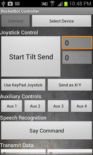
RocketBot offers several different remote control interfaces:
- Keypad: five buttons for forward, backward, left, right and stop. Exactly like the BlueStick app I implemented above.
- Joystick: X and Y values obtained from the phone accelerometer.
- Left/Right: individual controls for left and right motors, calculated from the phone accelerometer input.
The documentation describes the communication protocol in detail. For this controller all commands have two bytes, an operation byte and a data byte. A quick summary of the control codes I will be implementing (not the full list) is below:
"D1","D2","D3","D4","D5": Forward, Left, Right, Backward, and Stop respectively."A1","A2","A3","A4": Four auxiliary function buttons."X<number>","Y<number>": Joystick position. Values come in the 0-200 range, with 100 being the center position, 200 being full speed backward or right and 0 being full speed forward or left."L<number>","R<number>": Left/Right controls. Values come in the 0-200 range, with 100 being the center position, 200 being full speed forward and 0 being full speed backward, on each of the sides.
The implementation is a bit more complex than the BlueTick remote, but follows more or less the same style. Here is the full driver implementation:
/**
 * @file rocketbot_remote_control.h
 * @brief remote control driver for the RocketBot Android remote control app.
 * @author Miguel Grinberg
 */

#include "remote_control.h"

namespace Michelino
{
    class RemoteControl : public RemoteControlDriver
    {
    public:
        /**
          * @brief Class constructor.
          * @param from the value in the 0-100 range that maps to 0 in remote control units.
              Any values below from will be interpreted as 0.
          * @param to the value in the 0-100 range that maps to 255 in remote control units.
              Any values above to will be interpreted as 255.
          */
        RemoteControl(int from, int to) : RemoteControlDriver(),
            scaleFrom(from), scaleTo(to),
            lastKey(command_t::keyNone), lastX(100), lastY(100), lastL(100), lastR(100) {}

        virtual bool getRemoteCommand(command_t& cmd)
        {
            cmd.stop();
            cmd.key = command_t::keyNone;

            if (BTSerial.available() < 2)
                return false; // no commands available
            unsigned char ch = BTSerial.read();
            unsigned char data = BTSerial.read();
            switch (ch) {
                case 'D': // keypad
                    switch (data) {
                    case 1:
                        cmd.goForward();
                        break;
                    case 2: // down
                        cmd.turnLeft();
                        break;
                    case 3: // left
                        cmd.turnRight();
                        break;
                    case 4: // right
                        cmd.goBack();
                        break;
                    case 5: // stop
                    default:
                        cmd.stop();
                        break;
                    }
                    break;
                case 'X':
                    lastX = data;
                    cmd.joystick(scale(lastX), -scale(lastY));
                    lastL = lastR = 100;
                    break;
                case 'Y':
                    lastY = data;
                    cmd.joystick(scale(lastX), -scale(lastY));
                    lastL = lastR = 100;
                    break;
                case 'L':
                    lastL = data;
                    cmd.leftAndRightSliders(scale(lastL), scale(lastR));
                    lastX = lastY = 100;
                    break;
                case 'R':
                    lastR = data;
                    cmd.leftAndRightSliders(scale(lastL), scale(lastR));
                    lastX = lastY = 100;
                    break;
                case 'A': // function keys
                    switch (data) {
                    case 1:
                        cmd.key = command_t::keyF1;
                        break;
                    case 2:
                        cmd.key = command_t::keyF2;
                        break;
                    case 3:
                        cmd.key = command_t::keyF3;
                        break;
                    case 4:
                        cmd.key = command_t::keyF4;
                        break;
                    }
                    break;
                default:
                    break;
            }
            if (cmd.key != command_t::keyNone && cmd.key == lastKey) {
                // repeated key, ignore it
                return false;
            }
            lastKey = cmd.key;
            return true;
        }

    private:
        int scale(int value)
        {
            value -= 100;
            if (value >= 0) {
                if (value <= scaleFrom)
                    return 0;
                else if (value >= scaleTo)
                    return 255;
                return (value - scaleFrom) * 255 / (scaleTo - scaleFrom);
            }
            else {
                if (-value <= scaleFrom)
                    return 0;
                else if (-value >= scaleTo)
                    return -255;
                return -(-value - scaleFrom) * 255 / (scaleTo - scaleFrom);
            }
        }

    private:
        int scaleFrom;
        int scaleTo;
        command_t::key_t lastKey;
        int lastX;
        int lastY;
        int lastL;
        int lastR;
    };
};
Unfortunately the code to handle this remote is pretty long.
The RemoteControl class constructor for this controller takes two arguments. These are used to scale the values returned by the remote. For example, setting from = 10 and to = 50 will make this driver report a 0 value for the first 10% of the tilt range in every direction and reach the maximum at the 50% tilt position. This helps in two ways. First, if you hold the phone in your hand it would be impossible to keep it at a perfect zero tilt to make the vehicle stop, so with from = 10 there is a small range of tilt that will not affect the motors. Second, with to = 50 I can reach the maximum position with the phone at 45 degrees instead of a full 90 degrees in each direction.
The constructor also initializes a few member variables that remember the last known values for the different controller values. These variables are necessary because the protocol this remote uses does not send the whole information in a single command, instead each command sends only one value, so for example, when I get an updated X value I need to know what Y to use, so I take it from my lastY member variable.
The getRemoteCommand() method is structured similarly to the previous driver, but here I need to read two bytes from the serial port instead of one and I have a larger number of commands to handle in the switch statement.
The handling of the D and A commands is similar to the other driver. Here is the snippet that handles the new commands in this controller:
                case 'X':
                    lastX = data;
                    cmd.joystick(scale(lastX), -scale(lastY));
                    lastL = lastR = 100;
                    break;
                case 'Y':
                    lastY = data;
                    cmd.joystick(scale(lastX), -scale(lastY));
                    lastL = lastR = 100;
                    break;
                case 'L':
                    lastL = data;
                    cmd.leftAndRightSliders(scale(lastL), scale(lastR));
                    lastX = lastY = 100;
                    break;
                case 'R':
                    lastR = data;
                    cmd.leftAndRightSliders(scale(lastL), scale(lastR));
                    lastX = lastY = 100;
                    break;
The driver could be sending X and Y commands, or it could be sending L and R depending on which mode it is in. Any time I get a command I save it in the proper member variable, and then I use the appropriate conversion function to set the command_t struct.
Note that I have an auxiliary function called scale() that takes care of the scaling using the from and to values given in the constructor.
Also interesting to note that when I get an X or Y command I reset both the lastL and lastR, to make sure I don't keep any older values these two may have had before. Likewise, when I get an L or R I reset the lastX and lastY.
Final words
The updated firmware can be downloaded from github:
Download michelino v0.3, or clone it.
As always, I welcome your questions. Feel free to drop a comment below if there is anything you did not understand or need clarification on.
With the last major piece of my robot firmware completed I could call the project done. Unfortunately I'm not satisfied that easily, even though I have fully achieved the goals I stated at the start of this tutorial series I now have the itch to try other vehicle designs, which I will try to incorporate into my michelino firmware.
You may also want to keep track of the "master" branch of the project on github, as that's where updates will show up.
I'm particularly interested in supporting other motor controllers and more remote controls. If you have any you would like to see implemented let me know, or better yet, fork my project on github, implement it yourself and send me a pull request to get it included in the official project.
Thank you for following me on this tutorial, I hope my articles were of help to you. Best of luck with your Arduino based projects!
Miguel
Become a Patron!
Hello, and thank you for visiting my blog! If you enjoyed this article, please consider supporting my work on this blog on Patreon!

-
#176 Miguel Grinberg said
@anirudh: there is only one sketch, the .ino file. The other files are not sketches, they are header files.
-
#177 Matt said
Hi, thanks for the tutorial.
I have everything set up and all the other programs have worked, but the bluestick doesn't control it. The blinking light becomes a solid red but it doesn't move. I have tested all the parts separately and they all work on their own. When I press a button in the bluestick app in the serial monitor the line
state: 3, currentTime: 25449, distance: 200 remote: (0,l:0,r:0,k:0)
changes to
state: 3, currentTime: 25449, distance: 200 remote: (1,l:0,r:0,k:0)
but it doesn't move, do you have any suggestions? -
#178 Miguel Grinberg said
@Matt: the logging seems to indicate the commands are being received, but they are ignored. You need to add additional logging in the bluestick_remote_control.h file to see what are you reading from bluetooth. For some reason it appears the sketch isn't getting valid data.
-
#179 Matt said
Hi,
Sorry, but how do I add additional logging to the bluestick_remote_control file? -
#180 acbzaw said
Thanks for the tutorial, I have the same problem as Matt. How would I add logging to the bluestick file?
-
#181 Miguel Grinberg said
@Matt and @acbzaw: just include "logging.h" in that file, and then add log() calls that dump the variables you want to see.
-
#182 Matt said
Hi,
I played around with the logging file and added the code from part 2 where it would output what was received
When I click the up arrow in bluestick it outputs this at the same time
state: 3, currentTime: 171752, distance: 3 remote: (0,l:0,r:0,k:0)
Received: 8
state: 3, currentTime: 171836, distance: 4 remote: (1,l:0,r:0,k:0)
Received: 0
Is it supposed to output 0 after and it still doesn't move. suggestions? -
#183 Miguel Grinberg said
@Matt: I think the expected output would be:
Received: 8
state: 3, currentTime: 171836, distance: 4 remote: (1,l:255,r:255,k:0)This would make the two motors go forward at full speed. The "8" that the remote received should have cause the goForward() function to be called, and this function should have set the left and right variables to 255.
-
#184 Chou Chih-Her said
Hi Miguel:
Thanks! I can not compile.
I use :Arduino:1.6.5 (Windows 10), :"Arduino/Genuino Uno"
The edit line 121 : disply highlight remoteControl(REMOTE_CONTROL_INIT)
and the error information is : no matching function for call to 'Michelino::RemoteControll(int, int)'
and then the information as follows:
C:\Users\CHOU\Documents\Arduino\libraries\michelino3/bluestick_remote_control.h:11:11: note: candidate expects 1 argument, 2 provided
no matching function for call to 'Michelino::RemoteControl::RemoteControl(int, intHow can I do the debug ? Please. Thanks.
Chou Chih-Her Taipei,Taiwan
-
#185 Miguel Grinberg said
@Chou: my guess is that you are using the wrong remote control driver. The REMOTE_CONTROL_INIT macro needs to be defined specifically for your selected remote control driver, and the error suggests it isn't set correctly.
-
#186 Chou Chih-Her said
Hi Miguel:
<h1>define ENABLE_BLUESTICK_REMOTE_CONTROL_DRIVER</h1>
Thanks! It's OK.
// Remote control://#define ENABLE_ROCKETBOT_REMOTE_CONTROL_DRIVER
<h1>define ENABLE_ROCKETBOT_REMOTE_CONTROL_DRIVER</h1>
or
//#define ENABLE_BLUESTICK_REMOTE_CONTROL_DRIVERuse different romote app,(bluestick & rocketbot). they are no problem.
Thank you very much.
Chou Chih-Her Taipei,Taiwan
-
#187 Avery W said
Hi Miguel. I was just wondering if there is an app for IOS that can be used instead of bluestick or rocketbot.
-
#188 Miguel Grinberg said
@Avery: I don't know any because I don't use iOS devices, but search for it, there's got to be some.
-
#189 mariano said
Hi Miguel, first of all thanks for this blog.
I'm trying to get working the version michelino02, the problem I have is that when the robot goes i the state turning it stop and does not move anymore.
From the logs i can see that the sound sensor is working, I have also tested the motor with the simple sketch you post to test the motor and it works.
Do yo have some Idea how I can debug the problem? -
#190 Miguel Grinberg said
@mariano: the logs that the sketch prints over the serial connection should give you an idea of what's going on. I specifically refer to this: https://github.com/miguelgrinberg/michelino/blob/master/michelino.ino#L123-L125. If you look at the progression of those logs, you should be able to figure out why the robot isn't doing what it's supposed to.
-
#191 Patrick said
I know 4 years have passed but I am trying to build this robot and everything works great ( thanks to your awesome guide ) except the bluetooth remote control. Using this piece of code:
<h1>define BT_RX_PIN 16</h1> <h1>define BT_TX_PIN 17</h1> <h1>include <SoftwareSerial.h></h1>SoftwareSerial BTSerial(BT_RX_PIN, BT_TX_PIN);
void setup()
{
Serial.begin(9600);
BTSerial.begin(9600);
}void loop()
{
if (BTSerial.available() > 0) {
Serial.print("Bluetooth is ready!");
char ch = BTSerial.read();
Serial.print("Received: ");
Serial.println(ch);
}
}I can read perfectly well the characters that the bluetooth module is sending. Using your code though I can not. I have separate power supplies for the motors and for the arduino ( Arduino Uno ). Any help please?
-
#192 Miguel Grinberg said
@Patrick: can't really think of a reason. Have you tested your code while every other component is connected? Maybe there is a collision between them?
-
#193 David said
I know this is an old thread but I was hoping to get some help with your firmware. I 'm trying to build this robot with my kid but instead of the Adafruit moto shield you used, I have a L298N motor shield.
The arduino IDE downloaded these libraries (https://github.com/AndreaLombardo/L298N)
but I can't make your firmware work with that (or my limited coding knowledge isn't helping).
Can you help? -
#194 Miguel Grinberg said
@David: Yes, your motor shield will need a different driver. You will need to take the Adafruit driver that I wrote and adapt the setSpeed() method so that it uses the library that you have for your L298N.
-
#195 Prasanna K said
Thanks for this great blog! Can you please help me with the error message below ?
Arduino: 1.8.8 (Windows 7), Board: "Arduino/Genuino Uno"
C:\Users\myPC\AppData\Local\Temp\ccVZuHu6.ltrans0.ltrans.o: In function `getRemoteCommand':
sketch/bluestick_remote_control.h:21: undefined reference to `Michelino::RemoteControlDriver::command_t::stop()'
sketch/bluestick_remote_control.h:29: undefined reference to `Michelino::RemoteControlDriver::command_t::goForward()'
sketch/bluestick_remote_control.h:32: undefined reference to `Michelino::RemoteControlDriver::command_t::goBack()'
sketch/bluestick_remote_control.h:35: undefined reference to `Michelino::RemoteControlDriver::command_t::turnLeft()'
sketch/bluestick_remote_control.h:38: undefined reference to `Michelino::RemoteControlDriver::command_t::turnRight()'
collect2.exe: error: ld returned 1 exit status
exit status 1
Error compiling for board Arduino/Genuino Uno.This report would have more information with
"Show verbose output during compilation"
option enabled in File -> Preferences. -
#196 Miguel Grinberg said
@Prasanna: well, you have some undefined references. Have you defined the stop(), goForward() and so on methods?